
Motor controlling device, motor drive system, method of motor control, semiconductor device and electronic device

a technology of motor control and control device, which is applied in the direction of electronic commutators, motor/generator/converter stoppers, dynamo-electric converter control, etc., can solve the problem of longer time and achieve the effect of high controllable speed, control cost, and control cos

Inactive Publication Date: 2011-07-12
KK TOSHIBA
View PDF8 Cites 9 Cited by
  • Summary
  • Abstract
  • Description
  • Claims
  • Application Information

AI Technical Summary

Benefits of technology

The present invention provides a motor control device that can restrain cost increase, achieve higher processing speed, and provide good controllability. The device includes a position detection unit that performs an analog computation process for induced voltages of the motor based on a phase voltage equation, and a digital processing unit that generates a sinusoidal PWM signal based on the rotational position signal, thereby controlling the motor. The invention also provides a motor control system that includes the motor, the position detection unit, and the digital processing unit, and an inverter circuit that drives the motor based on the PWM signal. The invention further provides an electronic device that includes the position detection circuit and the microcomputer for generating the sinusoidal PWM signal. The motor control method and system can control costs and achieve high speed and high controllability.

Problems solved by technology

However, the computation for execution of position sensorless drive imposes heavy processing load on microcomputer software and accordingly necessitates longer time.

Method used


Image

  • Motor controlling device, motor drive system, method of motor control, semiconductor device and electronic device
  • Motor controlling device, motor drive system, method of motor control, semiconductor device and electronic device
  • Motor controlling device, motor drive system, method of motor control, semiconductor device and electronic device

Examples


first embodiment

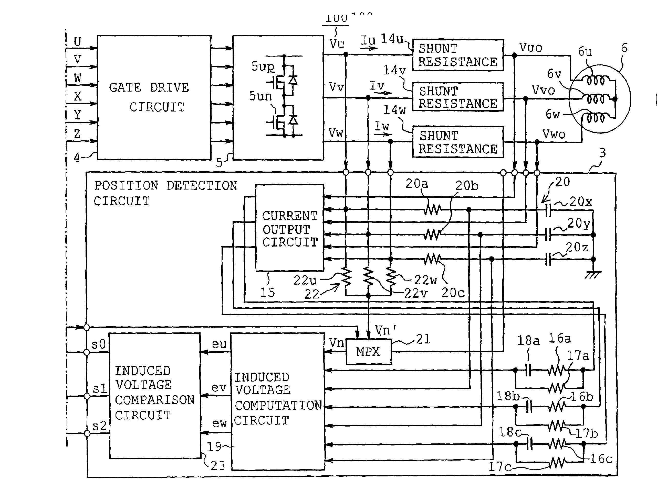
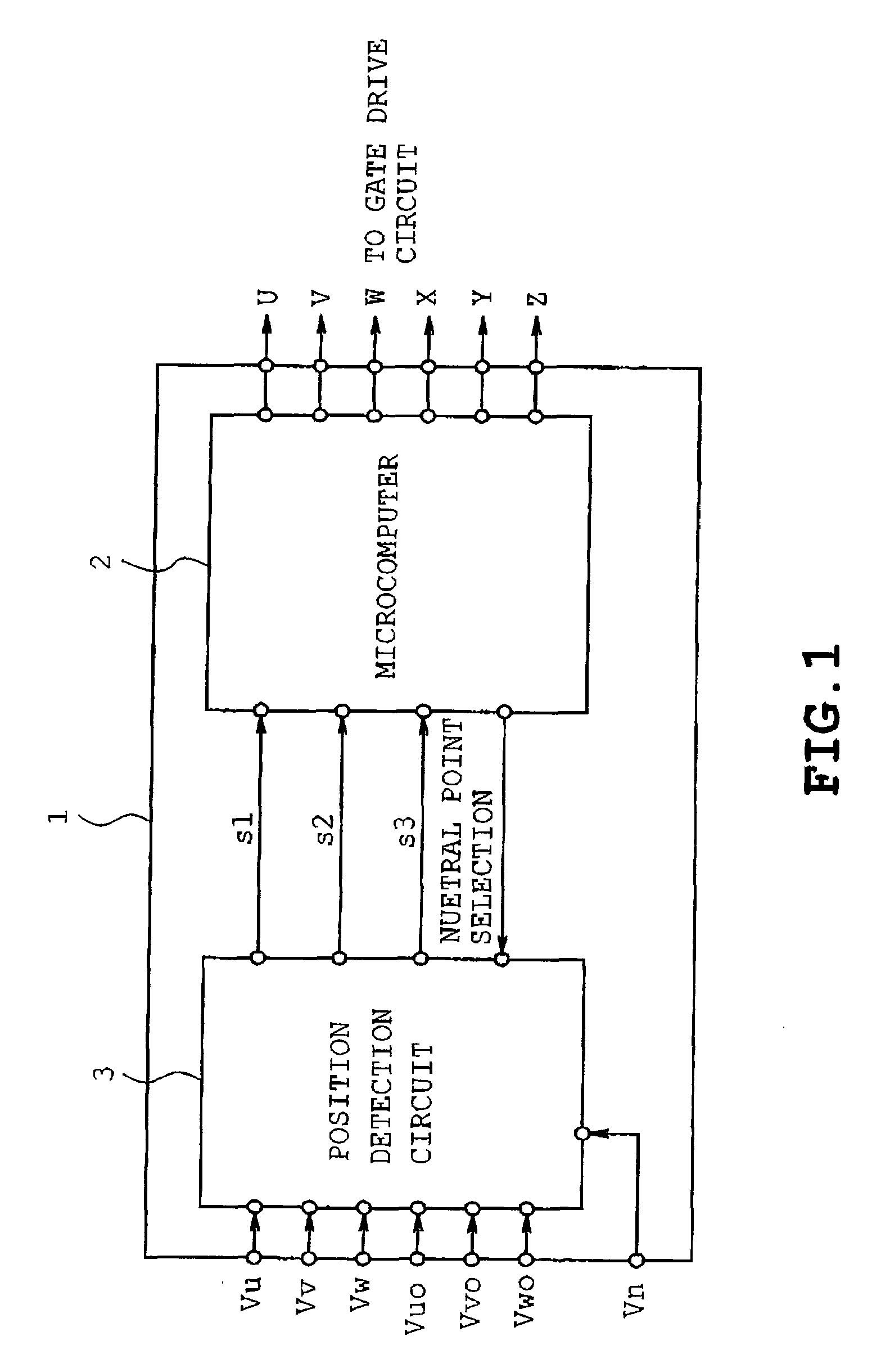
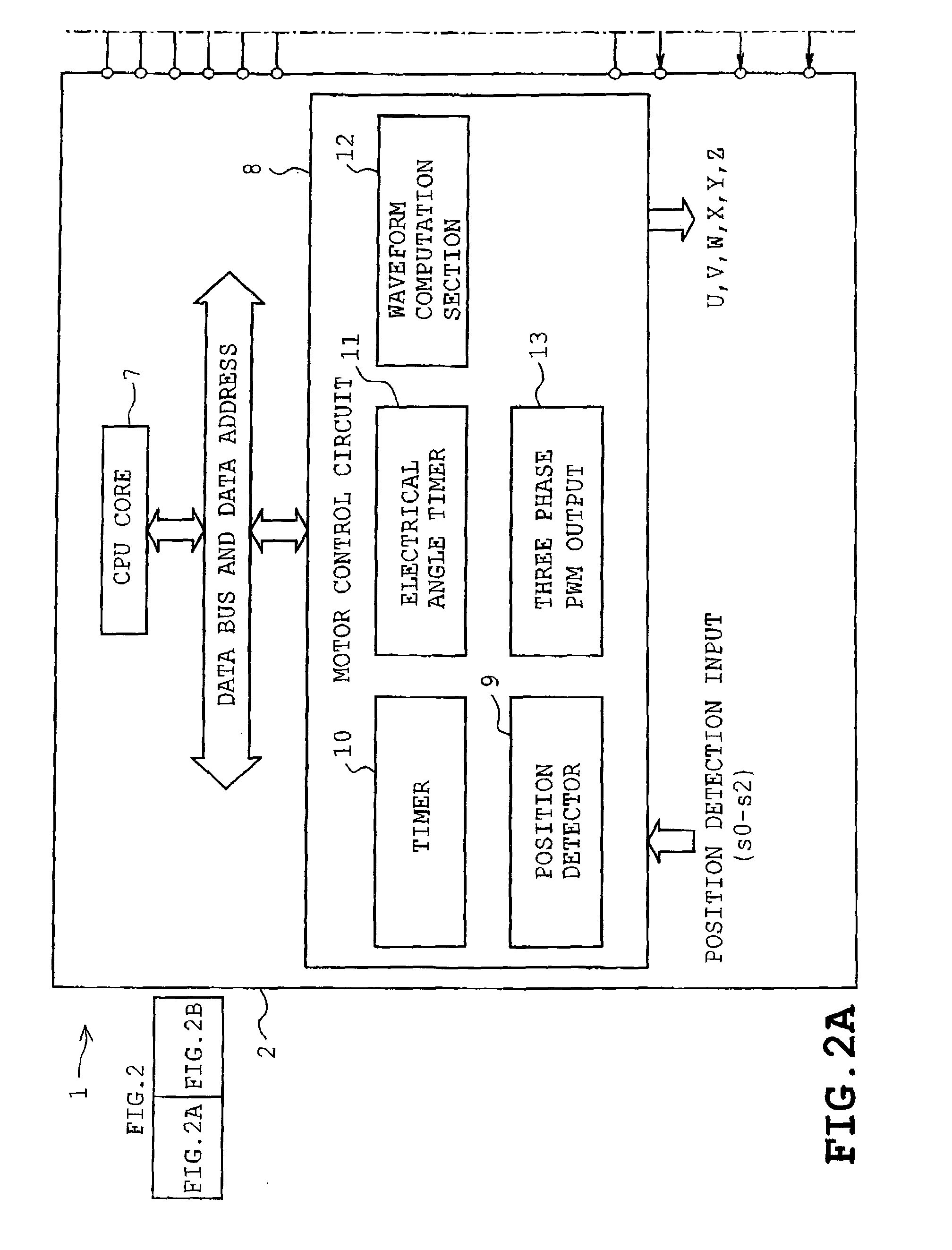
[0027]the present invention will be described with reference to FIGS. 1 to 9. Referring to FIG. 1, a drive control IC 1 for a brushless DC motor is shown. The drive control IC 1 or semiconductor device (or semiconductor integrated circuit device) or a motor control device comprises a microcomputer 2 with a function of performing a sine wave drive of an electric motor by a PWM control and a position detection circuit 3. An 8-bit microcontroller model TMP88CH41 manufactured by the assignee, Toshiba Corporation, Tokyo is exemplified as the above-mentioned drive control IC 1. When housed in a single IC package, the drive control IC 1 may be regarded as a microcomputer.

[0028]Referring now to FIGS. 2A and 2B, a brushless DC motor 6 is connected via a gate drive circuit 4 and an inverter circuit 5 to the drive control IC 1. The brushless DC motor 6 may be a spindle motor for turning a recording media such as a digital versatile disc (DVD), a compact disc (CD) or a hard disc drive (HDD). Al...

second embodiment

[0048]The operation of the drive control IC 51 will now be described. In the second embodiment, the microcomputer 2A carries out selection of either the position signals s0 to s2 delivered by the position detection circuit 3 or the voltage signals supplied to the input terminals Vu, Vv and Vw of the drive control IC 51 or position signals detected by Hall ICs as in the conventional manner, for example.

[0049]As the result of the above-described arrangement, the drive control IC 51 can easily be used as a substitute for an arrangement of combination of the microcomputer 2 and a position sensor such as Hall ICs. For example, a conventional product has been provided which comprises a Hall IC detecting a rotor position of a brushless motor and uses the microcomputer 2 to carry out sine wave drive The product is proposed to be upgraded to the position sensorless drive system. Furthermore, the drive control IC 51 has a package size, pin configuration and the like which are designed so as t...


PUM


Abstract

A motor control device is disclosed which is arranged so as to perform a PWM control for a permanent magnet motor including a rotor having a permanent magnet and a stator with a multiphase winding. The motor control device includes a position detection unit which executes an analog computation process for induced voltages of respective phases of the motor based on a phase voltage equation having, as operation terms, respective phase voltages, respective phase currents, winding inductance, winding resistance and a neutral point voltage, the winding inductance and the winding resistance being motor constants of the motor, thereby generating and delivering a rotational position signal of the rotor based on a phase relation of the induced voltages, and a digital processing unit which has a function of generating and delivering a sinusoidal PWM signal based on the rotational position signal, thereby controlling the motor.

Description

CROSS-REFERENCE TO RELATED APPLICATIONS[0001]This application is based upon and claims the benefit of priority from the prior Japanese Patent Application No. 2007-172674 filed on Jun. 29, 2007, the entire contents of which are incorporated herein by reference.BACKGROUND OF THE INVENTION[0002]1. Field of the Invention[0003]The present invention generally relates to a permanent magnet motor comprising a rotor having permanent magnets and a stator provided with a multiphase winding, and more particularly to a motor control device and method for controlling the permanent magnet motor by a pulse width modulation (PWM) technique, and a motor drive system including the motor control device.[0004]2. Description of the Related Art[0005]A position sensorless control system is conventionally known as a technique for obtaining a rotational position signal of a rotor from motor voltage, current or the like by computation without use of Hall ICs etc., thereby controlling a brushless DC motor base...

Claims


Application Information

Patent Timeline
Patent Type & Authority Patents(United States)
IPC IPC(8): H02P6/00H02P6/18H02P6/06H02P6/08H02P6/182H02P6/21
CPCH02P6/182
Inventor HASEGAWA, YUKIHISANAGAI, KAZUNOBU
Owner KK TOSHIBA
Learn More