Image display apparatus with particular electron emission region location
a technology of electron emission region and image display apparatus, which is applied in the manufacture of electrode systems, electric discharge tubes/lamps, discharge tubes luminescnet screens, etc., can solve the problems of affecting image quality and long life of image display apparatus, long-term degradation of damage to electron emission elements over operation time. , to achieve the effect of reducing long-term degradation over operation time, high-quality images and long-term operation li
- Summary
- Abstract
- Description
- Claims
- Application Information
AI Technical Summary
Benefits of technology
Problems solved by technology
Method used
Image
Examples
first embodiment
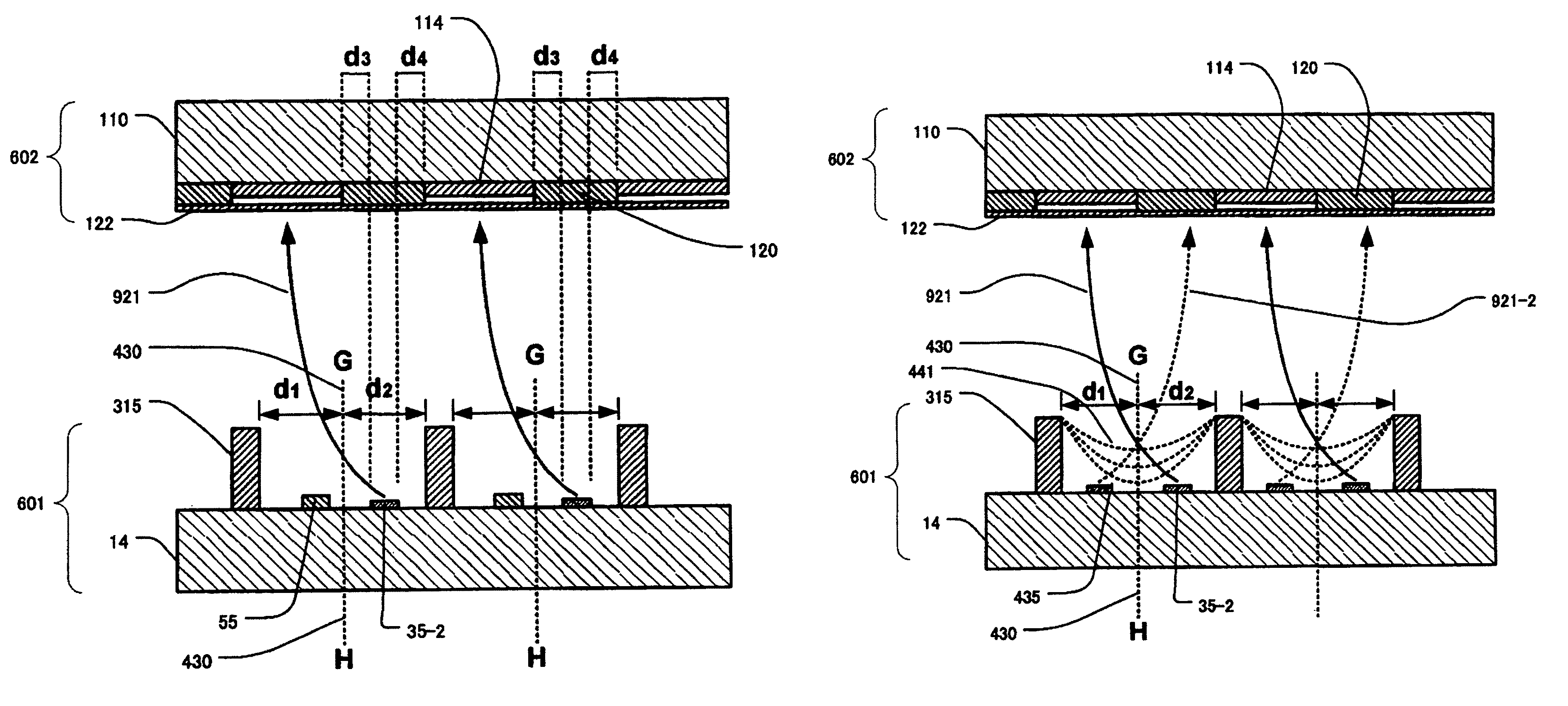
[0077]A first embodiment of the present invention is an example in a case when the present invention is applied to a MIM cathode, a surface conduction electron emitter element and the like. Here, first, a cause of degradation phenomenon of the electron emission element generated when operated in a state in which a high voltage is applied to a phosphor screen will be described.
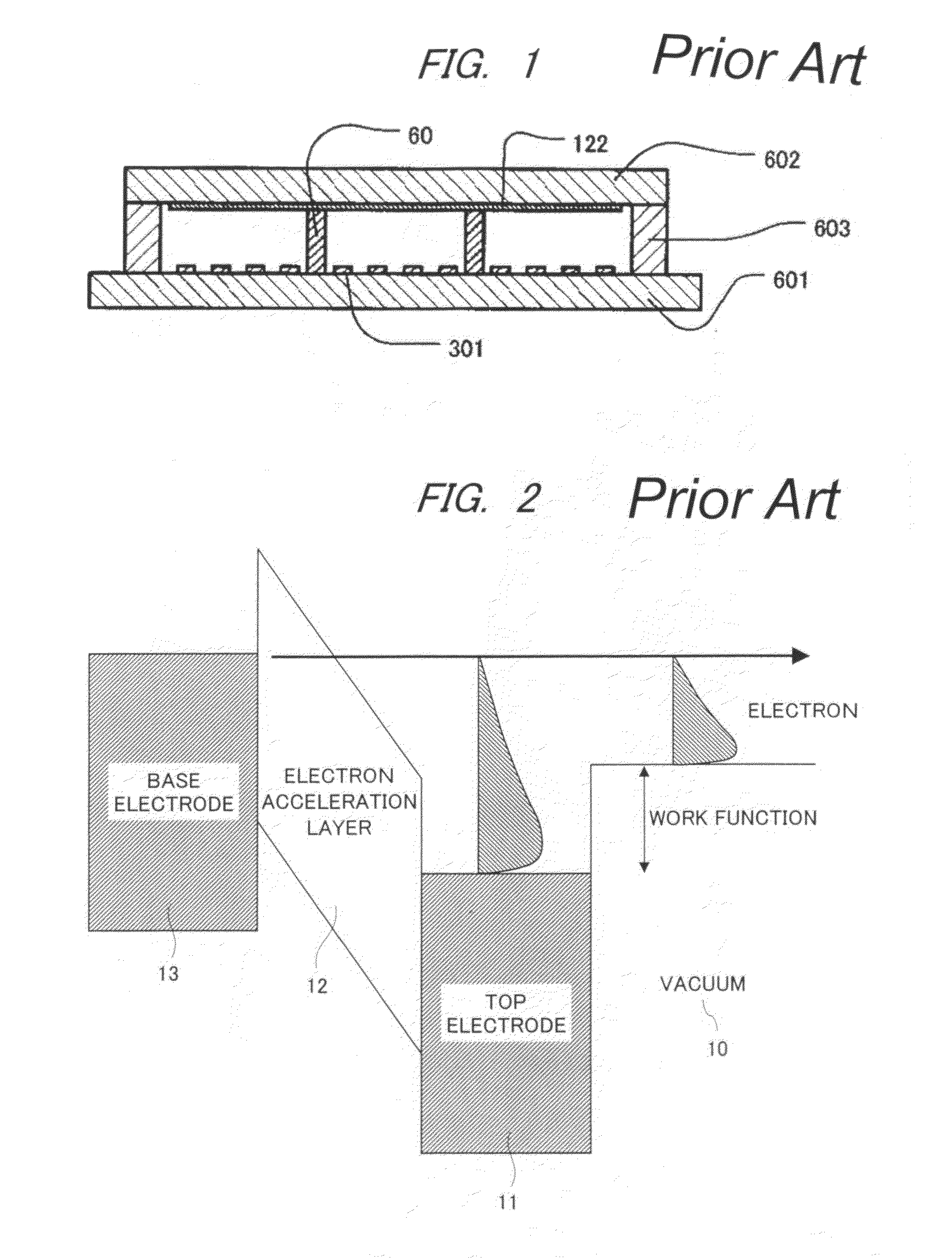
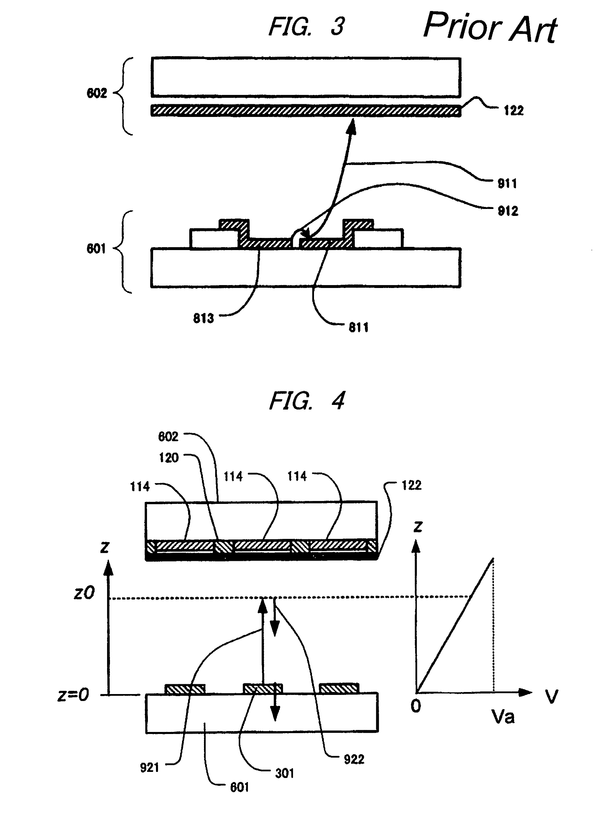
[0078]As described in FIG. 1, the electron emitted from an electron emission element 301 is accelerated by a phosphor-screen voltage Va, and after that, is bombarded onto or irradiated at an acceleration electrode 122 and a phosphor. Here, the phosphor-screen voltage means a voltage applied to the acceleration electrode 122, and it is typically Va=3 to 12 KV. When the electron accelerated to 1 KV or more bombards the phosphor and gas molecules, it is often that the electron ionizes atoms or molecules, thereby to generate positive ion. The positive ion is accelerated by the electric field between a phosphor plat...
second embodiment
[0098]A second embodiment of the present invention uses a thin film electron emitter as an electron emission element. As compared with another cathode such as a field emission type cathode, the thin film electron emitter is small in spatial divergence of emitted electron beam. The reason is as follows. In the thin film electron emitter, the electron accelerated in an electron acceleration layer is emitted into vacuum from a top electrode. In the thin film electron emitter, since the top electrode and a base electrode are mutually disposed in opposition in parallel, the electric field inside the electron acceleration layer is a uniform electric field. Since the electron is accelerated by this uniform electric field, the spatial divergence of the emitted electron becomes small. That the spatial divergence of the emitted electron beam is small is favorable characteristics because a high-resolution image display apparatus can be realized.
[0099]On the other hand, as evident from FIG. 4, ...
third embodiment
[0148]A third embodiment of the present invention will be described with reference to FIGS. 27 and 28A-28B. FIG. 27 is a top plan view of a cathode plate 601 constituting a display panel 100 used in the present embodiment. FIGS. 28A and 28B are cross section of the cathode plate 601, FIG. 28A is a cross section along line A-B of FIG. 27, and FIG. 28B shows a cross section along line C-D. When comparing the third embodiment with the second embodiment (FIGS. 13 and 14A-14B), the shape of a contact electrode 55 is different in the present embodiment. While the contact electrode 55 has a branch-shaped protrusion extending along the longer side of the electron emission region 35 in FIG. 13, the protrusion is not available in the present embodiment (FIG. 27).
[0149]As evident from FIG. 28B, a top electrode 11 is formed almost entirely on the surface except for a scan electrode 310 (that is, a busline electrode 32) and a deflection electrode 315. Since the film thickness (0.1 μm in the pres...
PUM
 Abstract
Description
Claims
Application Information
 - R&D
- Intellectual Property
- Life Sciences
- Materials
- Tech Scout
- Unparalleled Data Quality
- Higher Quality Content
- 60% Fewer Hallucinations
Browse by: Latest US Patents, China's latest patents, Technical Efficacy Thesaurus, Application Domain, Technology Topic, Popular Technical Reports.
© 2025 PatSnap. All rights reserved.Legal|Privacy policy|Modern Slavery Act Transparency Statement|Sitemap|About US| Contact US: help@patsnap.com


