
Refrigerant accumulation and oil recovery device for refrigerant fluid recovery/regeneration/recharging systems

a technology of refrigerant fluid and oil recovery device, which is applied in the direction of refrigerants, refrigeration components, refrigeration machines, etc., can solve the problems of compromising fluid efficiency, affecting the life of refrigerant fluid, and affecting the efficiency of fluid efficiency, etc., to reduce the possibility of refrigerant fluid leakage, prolong the life, and reduce the possibility of leakag

Inactive Publication Date: 2011-07-12
PARKER HANNIFIN S P A FLUID CONTROL DIV EURO
View PDF12 Cites 5 Cited by
  • Summary
  • Abstract
  • Description
  • Claims
  • Application Information

AI Technical Summary

Benefits of technology

"The patent text describes a new device for recovering, regenerating, and recharging refrigerant fluid from refrigeration or air conditioning plants. The device has several technical benefits compared to existing units. First, it has a longer life and greater reliability. Second, it reduces the possibility of refrigerant fluid leakage and minimizes the possible dispersion of refrigerant fluid into the environment. The device consists of a refrigerant accumulation and oil recovery vessel connected by fluid circuits to an oil recovery vessel, a compressor, a vacuum pump, an outlet for bleeding off the used oil, a make-up oil inflow connection, and an inlet connection for topping-up with fresh refrigerant. The device also includes a device for forming reliable seals and minimizing the possibility of leakage."

Problems solved by technology

The fluids currently used in refrigeration plants or heat pumps are known to be extremely costly.
In addition, the gases present in old installations are often damaging to the environment.
It is also sometimes necessary to “clean” and dehumidify the fluid present in such plants, such as when topping them up.
In this respect, this fluid is often contaminated by various impurities (such as sludge and metal particles) and by moisture due to prolonged system operation, or deriving from the topping-up operations themselves; These impurities compromise the fluid efficiency and can lead to plant malfunction.

Method used


Image

  • Refrigerant accumulation and oil recovery device for refrigerant fluid recovery/regeneration/recharging systems
  • Refrigerant accumulation and oil recovery device for refrigerant fluid recovery/regeneration/recharging systems
  • Refrigerant accumulation and oil recovery device for refrigerant fluid recovery/regeneration/recharging systems

Examples


Embodiment Construction

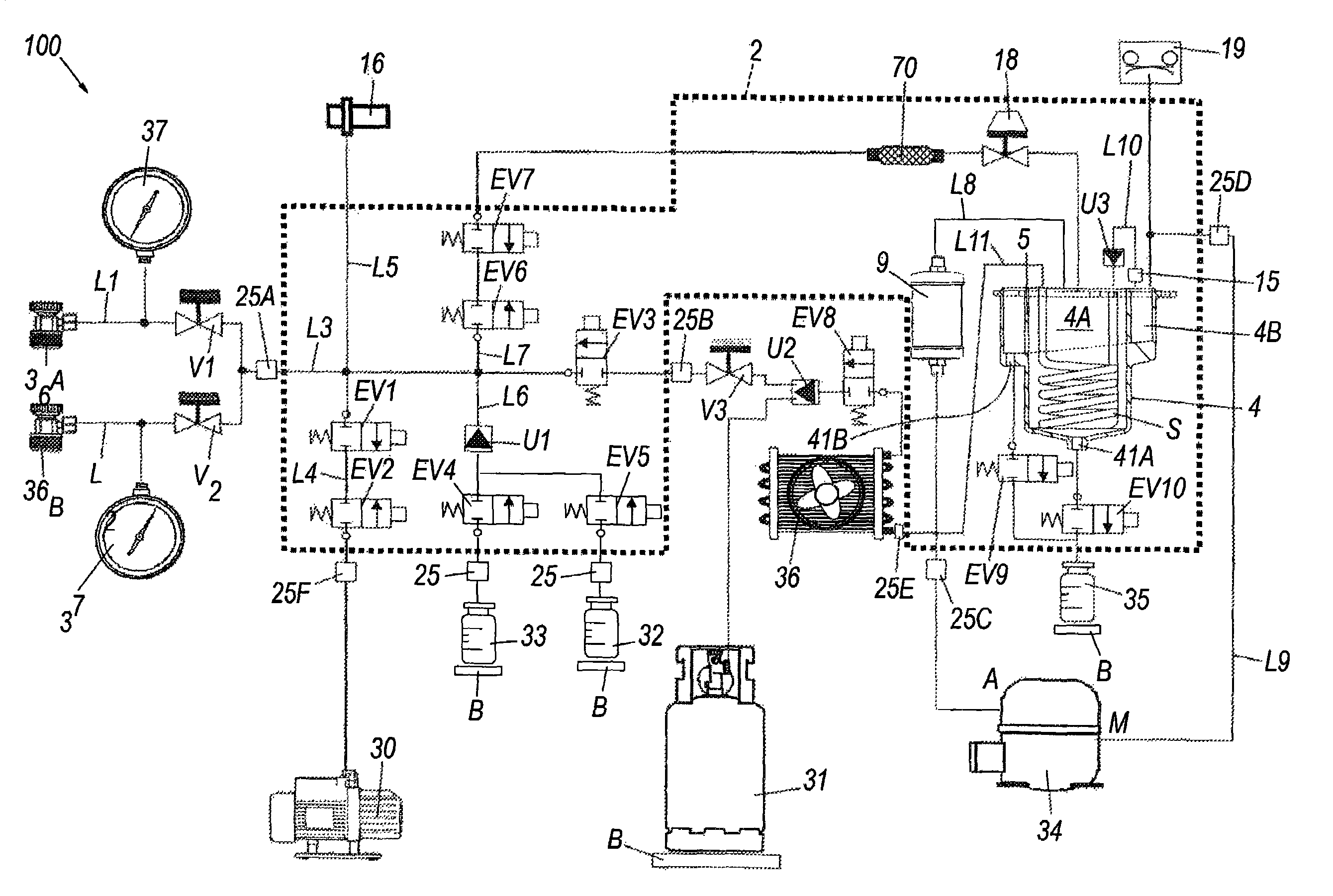
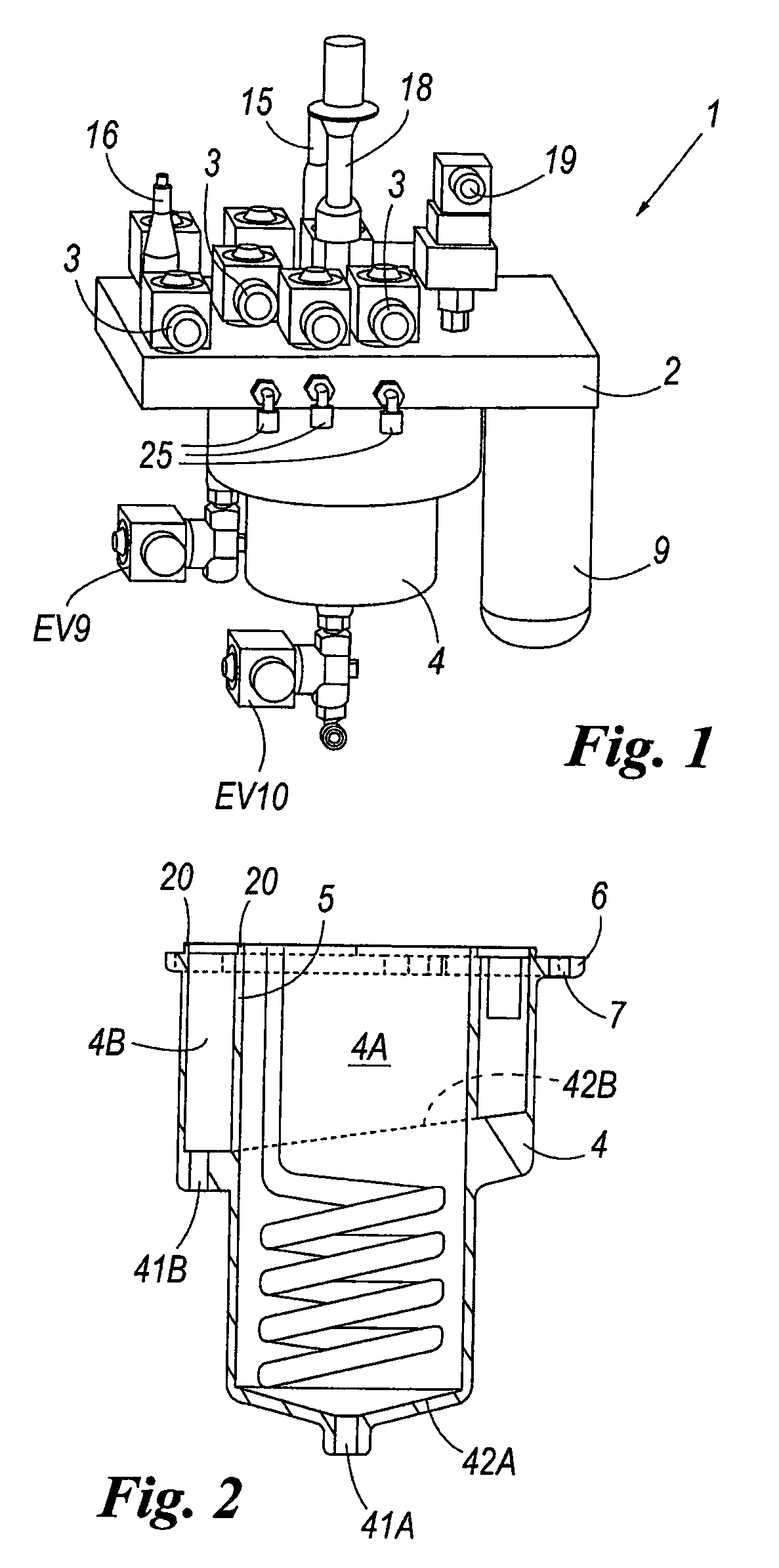
[0017]With reference to said figures, these show a refrigerant accumulation and oil recovery device indicated overall by the reference 1. This device forms part of a recovery / regeneration unit; an example of a regeneration unit is shown in FIG. 3. The device 1 comprises a plate 2 in which a plurality of fluid passages are provided. These passages are intercepted by suitable solenoid valves 3 which enable the refrigerant fluid flow through said passages to be deviated and controlled. A mechanical filter 15 (coalescent), a transducer 16, a constant pressure maintaining valve 18 and a pressure switch 19 are present above the plate 2 and suitably connected to said passages. A preferably metal alloy die-cast body 4 having the cross-section shown in FIG. 2 is fixed to the underside of the plate 2. It can be made of any material such as aluminium, steel or possibly reinforced plastic, for example by hot forging in the case of metals or by injection moulding in the case of plastic. This bod...


PUM


Abstract

A refrigerant accumulation and oil recovery device for recovery / regeneration / recharging units for a refrigerant fluid withdrawn from refrigeration or air conditioning plants or heat pumps, characterized by comprising a refrigerant fluid accumulation / evaporation vessel and an oil recovery vessel, said vessels being closed at their top by at least one plate which supports them both, the plate presenting a plurality of passages defining, with said vessels, a part of the charging / recycling circuit of said recovery / regeneration unit, in which said accumulation / evaporation vessel and said oil recovery vessel present at least one wall in common, such that any refrigerant fluid leakage from one of said vessels at the connection interface between said common wall and said plate is recovered into the other.

Description

CROSS REFERENCE TO RELATED APPLICATIONS[0001]The present application claims the benefit of the filing date of Italian Patent Application No. MI 2007A002100 filed on Oct. 31, 2007, the disclosure of which is incorporated herein by reference.BACKGROUND[0002]The present invention relates to a refrigerant accumulation and oil recovery device for refrigerant fluid recovery / regeneration systems.SUMMARY OF THE INVENTION[0003]It relates in particular to a recovery / regeneration / recharging system for a refrigerant fluid withdrawn from refrigeration or air conditioning plants or heat pumps. The fluids currently used in refrigeration plants or heat pumps are known to be extremely costly. In addition, the gases present in old installations are often damaging to the environment.[0004]There is hence a requirement to recover these gases when work has to be done on existing plants.[0005]It is also sometimes necessary to “clean” and dehumidify the fluid present in such plants, such as when topping th...

Claims


Application Information

Patent Timeline
Patent Type & Authority Patents(United States)
IPC IPC(8): F25B45/00
CPCF25B45/00F25B43/02F25B2345/006F25B2500/01
Inventor COLNAGHI, DARIOAVOLEDO, STEFANOMASCARELLO, OSVALDOBORSATTI, JEAN-CHARLES
Owner PARKER HANNIFIN S P A FLUID CONTROL DIV EURO
Learn More