Eureka AIR delivers breakthrough ideas for toughest innovation challenges, trusted by R&D personnel around the world.

Seat adjuster assembly

a seat and assembly technology, applied in the field of seat adjuster assembly, can solve the problems of easy damage, inability of plastic spur gear to withstand a large axial force by itself, etc., and achieve the effect of improving the design and structure of the seat adjuster assembly and reducing axial play

Active Publication Date: 2011-07-05
JOHNSON ELECTRIC SA
View PDF11 Cites 97 Cited by
  • Summary
  • Abstract
  • Description
  • Claims
  • Application Information

AI Technical Summary

Benefits of technology

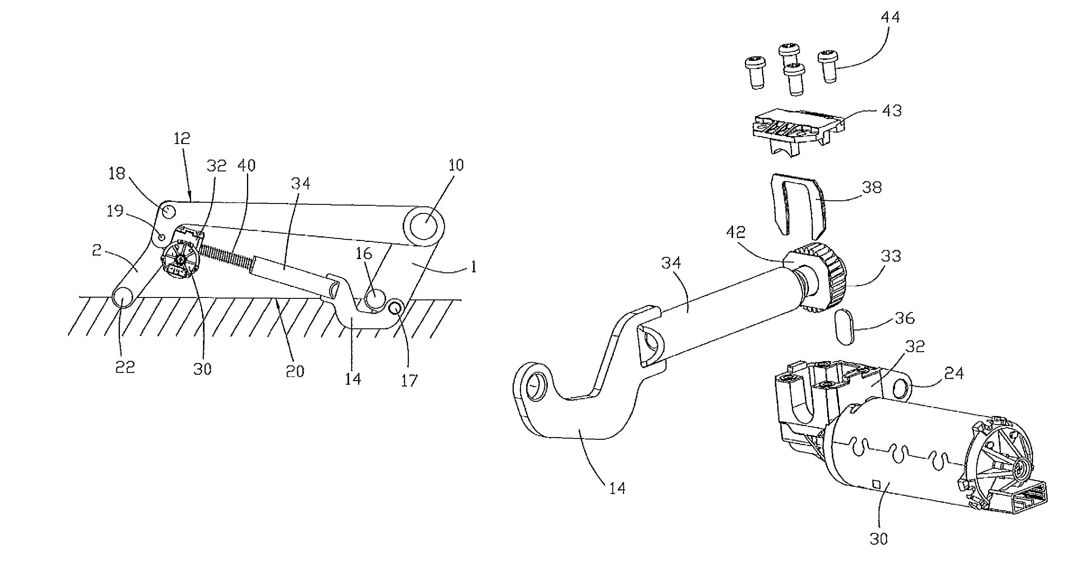
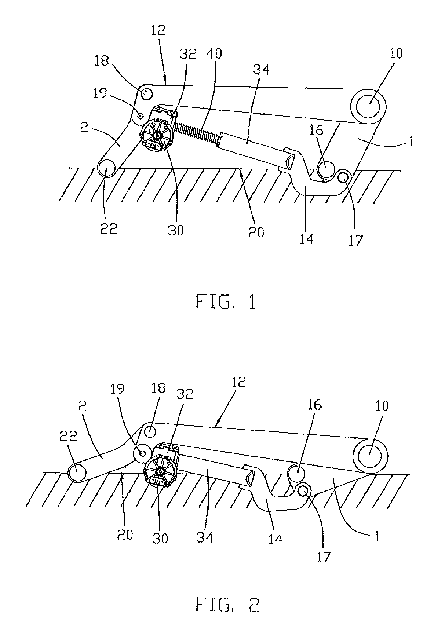
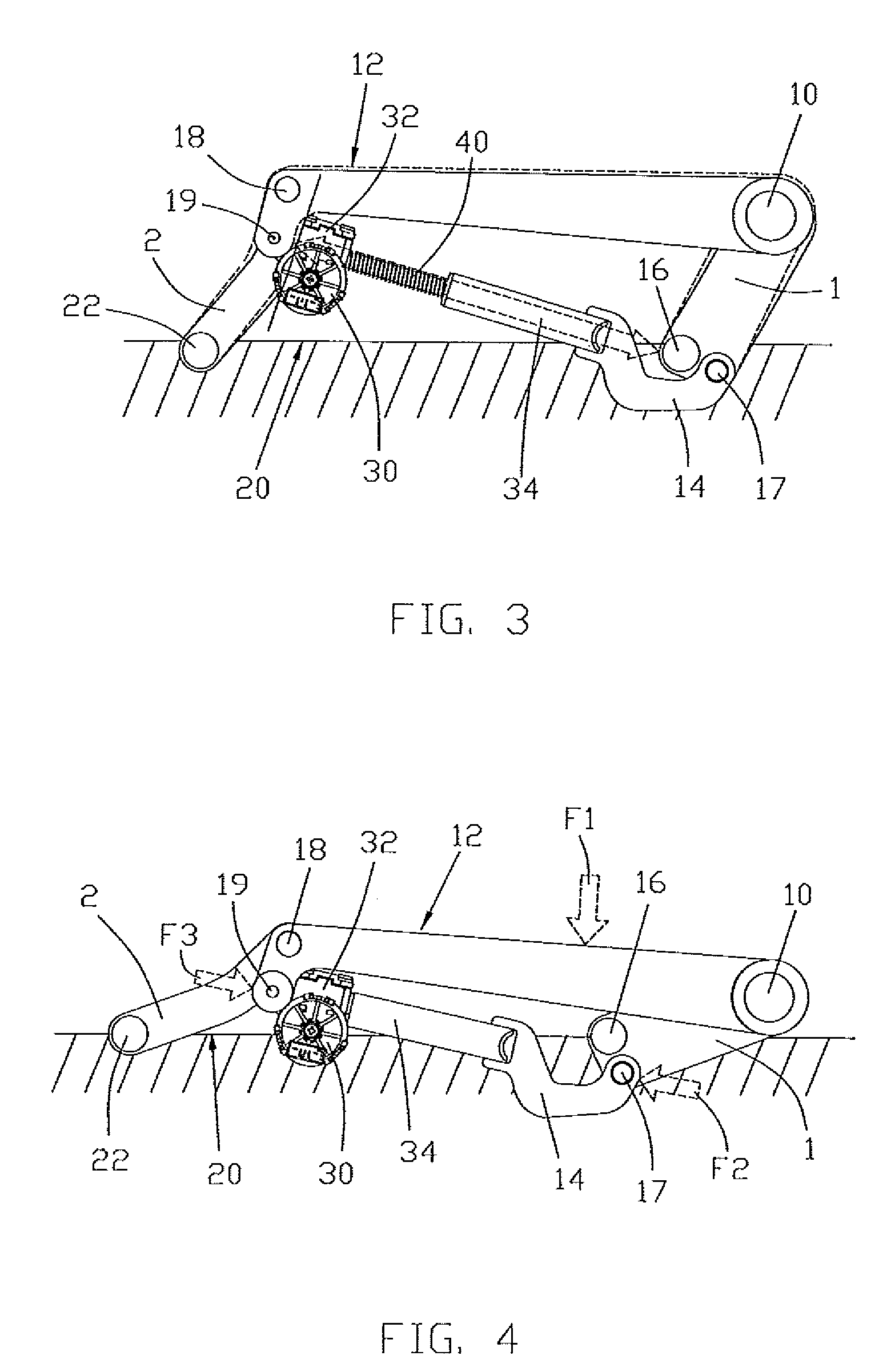
[0005]The main object of the present invention is to improve the design and structure of a seat adjuster assembly which can solve the above problems or which can reduce axial play in the motor sub-assembly.
[0006]The illustrated embodiments of the present invention have the beneficial effects of increasing the axial pull off force between the spur gear and the spindle shaft by using washers between the spur gear and the spindle shaft. Thus the present invention can greatly improve the security of the system in a simple manner.

Problems solved by technology

However, the plastic spur gear cannot withstand a large axial force by itself and is easily destroyed by a large axial force imposed on the spindle shaft, as would occur in the event of a crash or accident.

Method used


Image

  • Seat adjuster assembly
  • Seat adjuster assembly
  • Seat adjuster assembly

Examples


first embodiment

[0069]FIGS. 9 and 10 show the washer 46 that is provided on the spindle shaft 40 according to the present invention. A single washer 46 is pinched onto a necked portion of the spindle shaft to securely hold the washer in place during over-molding and to accept the axial loading of the spindle shaft. The washer 46 is a disc made of steel and consists of an annular split ring 47 with an opening 49 defined between two ends of the ring 47. Diametrically opposite the opening 49 is a slot 51 formed in the inner edge of the annular ring. The washer 46 is assembled onto a neck part, slightly diameter reduced section, of the spindle shaft 40, and then, the washer 46 is over-molded with the plastic gear 33. During assembly of the washer to the spindle shaft, the shaft is moved through the opening until the shaft is located within the annulus of the split ring. The washer is then squeezed or compressed to pinch the washer on to the shaft. In so doing the washer is plastically deformed so that ...

second embodiment

[0076]A second embodiment is shown in FIGS. 24A, 24B and 24C, in which four washers 46′ are provided on the neck part of the spindle shaft 40 and the gear 33 is molded over the four washers 46′. Each washer 46′ is a steel annular split ring 47′ with a U-shaped opening 49′ extending in radial direction thereof. The opening 49′ has a semi-circular end configured for contacting the spindle shaft 40. When all of the washers 46′ are stacked on the neck part of the shaft 40, the openings 49′ of the washers 46′ are distributed, preferably symmetrically, in the circumferential direction of the washers and the semi-circle ends of the openings 49′ are concentric with the shaft 40. The openings 49′ of each washer 46′ are closed by the rings or body portions of the other washers 46′ in the axial direction, which improves the anti-deforming capability of the washers 46′ greatly. It also provides the washers with a uniform outer circumference on which the spur gear is molded, to improve the quali...


PUM


Abstract

A seat adjuster assembly includes an electric motor having an output shaft with a worm gear positioned in a gearbox, a spur gear meshing with the worm gear in the gearbox, a spindle shaft fixed to and driven by the spur gear coacting with a nut contained in a tube, and a linkage system connected to both a vertically movable upper vehicle seat part and a non-vertically movable lower vehicle seat part that positions vertically the upper vehicle seat part responsive to the position of the nut relative to the spindle shaft. At least one washer is provided on the spindle shaft. The spur gear is a plastic spur gear molded over the washer. A pair of leaf springs disposed in the gearbox bears against the spur gear and a wall of the gearbox.

Description

CROSS REFERENCE TO RELATED APPLICATIONS[0001]This non-provisional patent application claims priority under 35 U.S.C. §119(a) from Patent Application No. 200810066076.9 filed in The People's Republic of China on Feb. 14, 2008 and from Patent Application No. 61 / 034,000 filed in USA on Mar. 5, 2008, the disclosure of each is incorporated herein by reference.FIELD OF THE INVENTION[0002]The present invention relates to a seat adjuster assembly and in particular to a motor assembly thereof.BACKGROUND OF THE INVENTION[0003]To fit different people, an automobile usually has a seat adjuster assembly which comprises a motor driving a spindle shaft via a gearbox. The spindle shaft has outer threads engaging with inner threads of a nut contained in a tube which in turn is connected to a linkage connected respectively to a vertically movable upper part of a vehicle seat and a non-vertically movable lower part of the vehicle seat to cause the seat to move up or down under the control of a passeng...

Claims


Application Information

Patent Timeline
Patent Type & Authority Patents(United States)
IPC IPC(8): B60N2/02A47C1/00
CPCB60N2/0232B60N2/1615B60N2/164H02K7/06H02K7/1166F16H25/20F16H2025/209B60N2/02246
Inventor ISHII, YOSHINORIWANG, ZHI SONG
Owner JOHNSON ELECTRIC SA
Why Eureka
Eureka Blog
Learn More