
Liquid discharging device and electro optic device

a technology of liquid crystal display and electrode, which is applied in the manufacture of electric discharge tubes/lamps, instruments, electrode systems, etc., can solve the problems of deteriorating display quality of liquid crystal display, and achieve the effect of improving thickness uniformity and improving optical characteristics

Inactive Publication Date: 2011-06-21
SEIKO EPSON CORP
View PDF8 Cites 5 Cited by
  • Summary
  • Abstract
  • Description
  • Claims
  • Application Information

AI Technical Summary

Benefits of technology

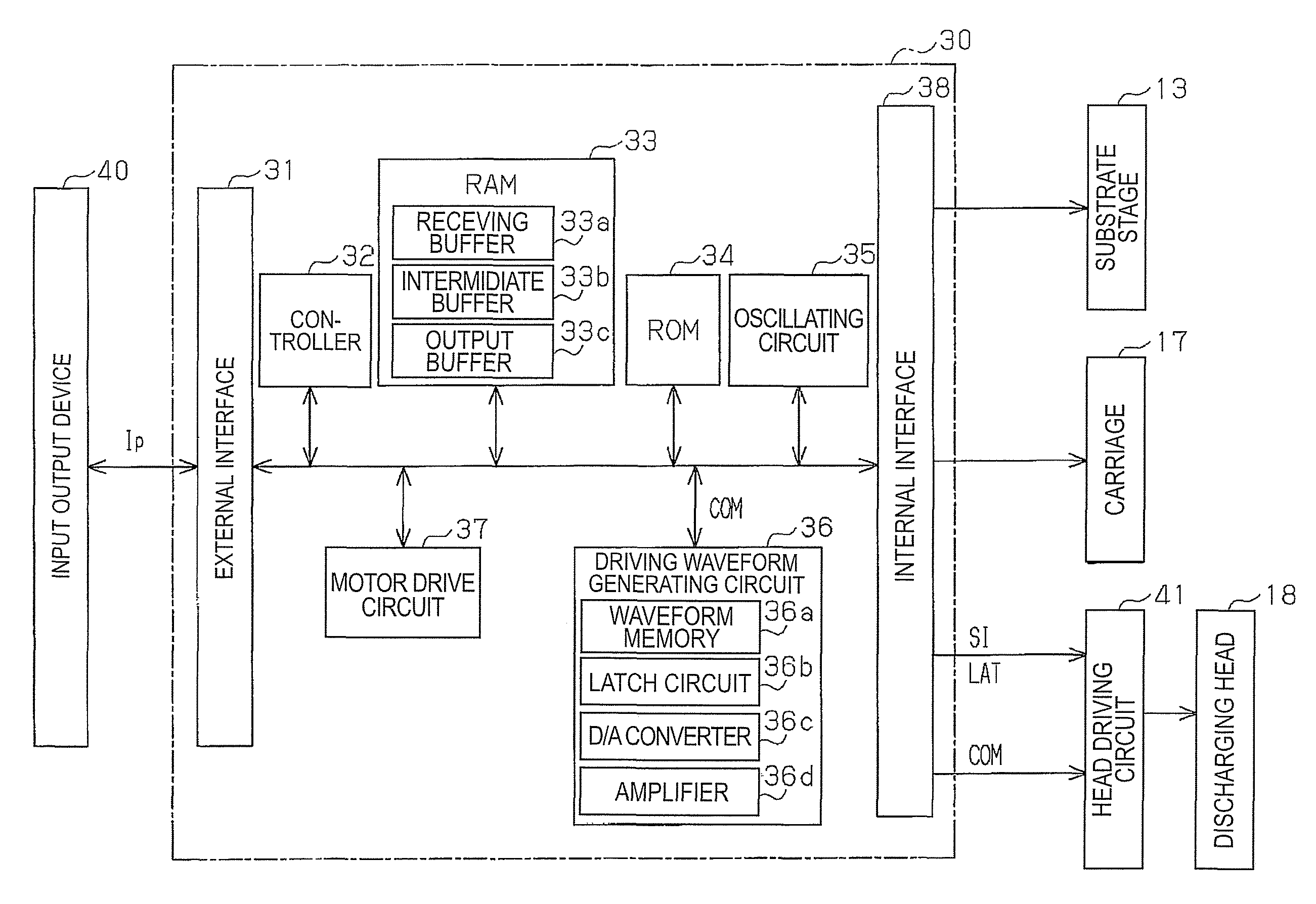
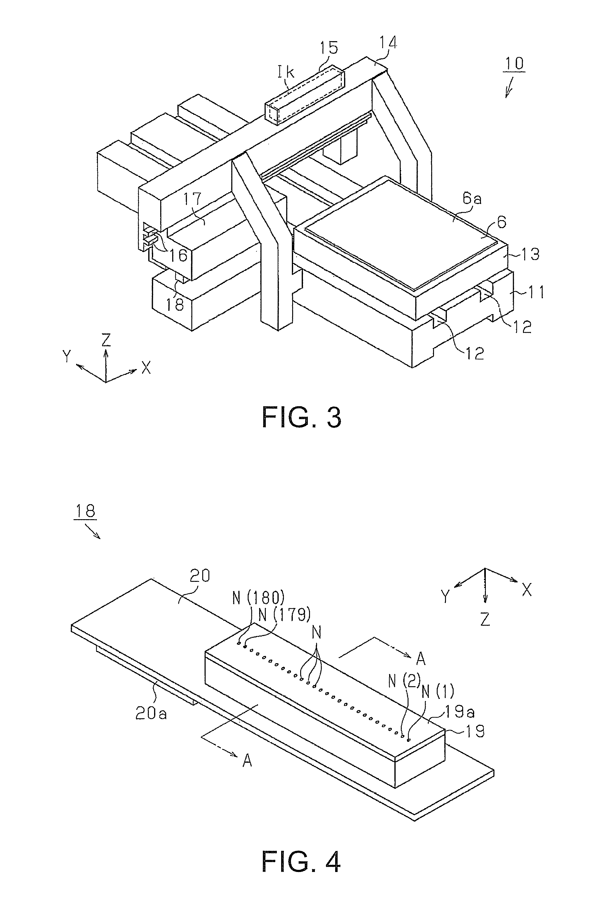
The present invention provides a droplet-discharging head that improves thickness uniformity of film patterns formed by discharging liquid droplets. The invention includes a droplet-discharging device that has a plurality of nozzles that discharge liquid droplets and a scanning unit for relatively moving the droplet-discharging head and a substrate. The device also includes a memory for memorizing pattern data corresponding to driving nozzles and a transferring unit for developing the patterned data into a plurality of data to be divided and transferred to the droplet-discharging head. The patterned data is data that allocates the nozzles to different blocks and each block corresponds to a different discharged region. The device can improve thickness uniformity of a film pattern formed by discharging liquid droplets and can also improve the optical characteristics of the electro optic device that includes the thin film formed by the process of discharging liquid droplets.

Problems solved by technology

Such providing, however, causes a following problem.
As a result, relatively large sized droplets or relatively small sized droplets are continuously discharged along a scanning line, forming thickness steps along a scanning line of a droplet-discharging head and remarkably deteriorating display quality of an liquid crystal display.

Method used


Image

  • Liquid discharging device and electro optic device
  • Liquid discharging device and electro optic device
  • Liquid discharging device and electro optic device

Examples


Embodiment Construction

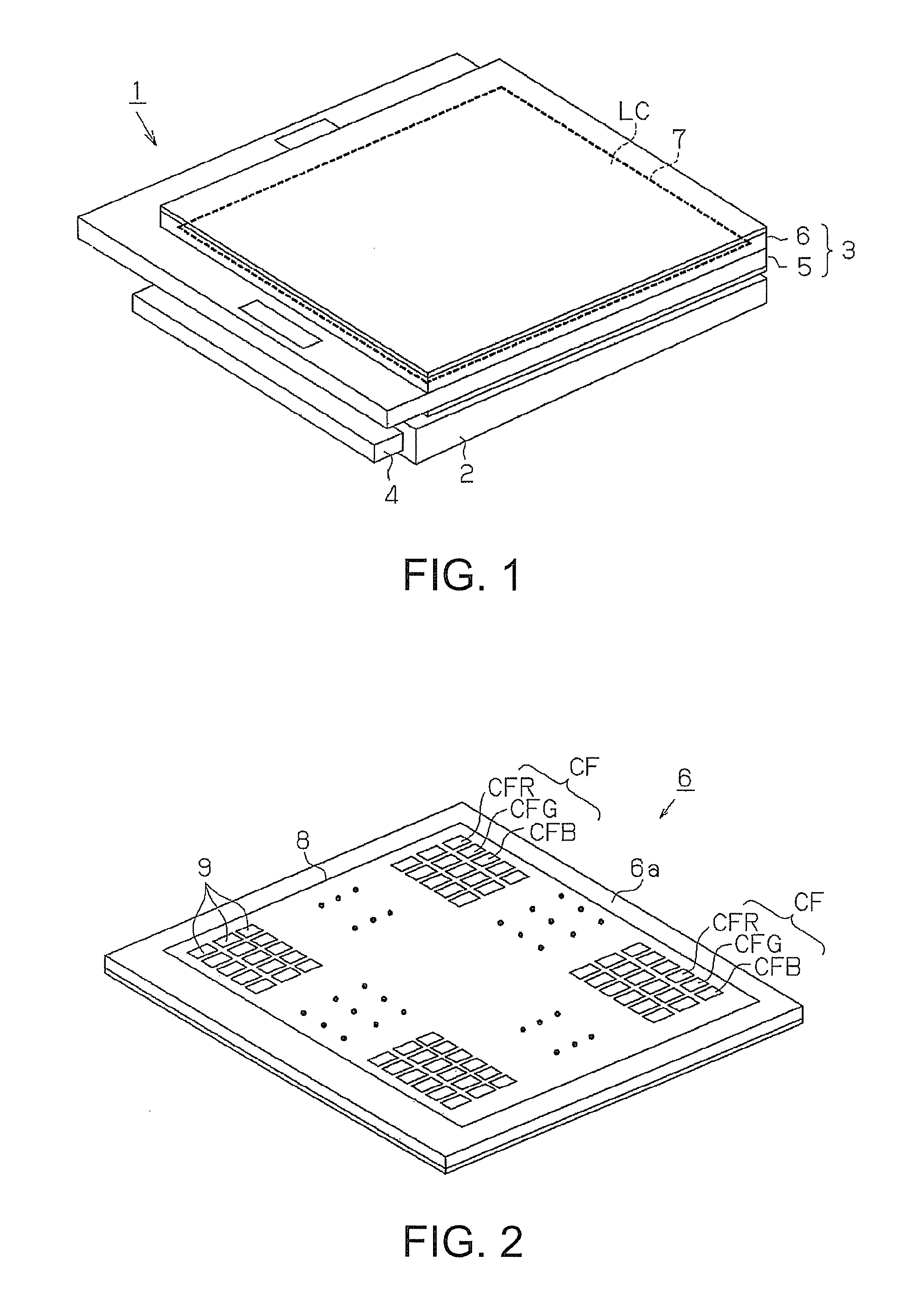
[0029]Embodiments of a invention will be described with reference to the accompanied drawings from FIG. 1 to FIG. 9. First, a liquid crystal display 1 as an electro optic device is explained. FIG. 1 is a perspective view of a liquid crystal display. FIG. 2 is a perspective view showing a color filter substrate provided with the liquid crystal display.

[0030]As shown in FIG. 1, a liquid crystal display 1 comprises a backlight 2 and a liquid crystal panel 3. The backlight 2 irradiates an entire surface of the liquid crystal panel 3 with light emitted from a light source 4. The liquid crystal panel 3 comprises a element substrate 5, a color filter substrate 6, a sealing member 7 having rectangular frame for attaching these two substrates together and a liquid crystal LC encapsulated between these two substrates. The liquid crystal LC displays desired images on an upper surface of the color filter substrate 6 by modulating light from the backlight 2.

[0031]In FIG. 2, a light shielding lay...


PUM


Abstract

A liquid droplet-discharging device comprises: a droplet-discharging head having a plurality of nozzles that are arranged in a predetermined direction and discharge liquid droplets; a scanning unit for relatively moving the droplet-discharging head and a substrate toward a scanning direction: a memory memorizing pattern data corresponding to driving nozzles that are selected from the plurality of nozzles in each of a plurality of discharged regions, by partitioning a drew region of the substrate into the plurality of discharged regions every discharging frequency along a scanning direction of the substrate; a transferring unit for developing the patterned data memorized by the memory into a plurality of data to be divided and transferring the divided data to the liquid droplet-discharging head in order; and an output unit for outputting a driving signal that drives a driving nozzle selected by the divided data to discharge the liquid droplets. The patterned data are data that allocates the plurality of nozzles to a plurality of blocks and corresponds each of the plurality of blocks to each of the plurality of discharging regions.

Description

BACKGROUND OF THE INVENTION[0001]1. Technical Field[0002]A present invention relates to a droplet-discharging device and an electro optic device.[0003]2. Related Art[0004]A liquid crystal display generally comprises oriented liquid crystal molecules and an orientational film made of orientational polymer such as orientational polyimide, which arranges orientation of liquid crystal molecules. An ink jet method using a droplet-discharging head is applied to a process for manufacturing the oriented film in order to improve productivity and reduce a manufacturing cost. (see JP-A-2004-347694.)[0005]The droplet-discharging head comprises a plurality of cavities storing liquid, a plurality of nozzles arranged in a row and connected to cavities, and a plurality of actuators such as piezoelectric elements and resistive heating elements. The droplet-discharging head receives input signals that commonly drive an actuator selected among a plurality of actuators based on drawing data and dischar...

Claims


Application Information

Patent Timeline
Patent Type & Authority Patents(United States)
IPC IPC(8): B41J29/38
CPCG02F1/1337G02F1/13
Inventor ISHIDA, KOHEI
Owner SEIKO EPSON CORP
Learn More