Combustion air supply arrangement

a technology of combustion air supply and compressor, which is applied in the direction of engine components, carburetors, engine controllers, etc., can solve the problems of compressor sucking in air and compressing, screw compressor running harder, and the risk of overloading other components

Inactive Publication Date: 2011-06-14
KOENIGSEGG AUTOMOTIVE
View PDF23 Cites 7 Cited by
  • Summary
  • Abstract
  • Description
  • Claims
  • Application Information

AI Technical Summary

Benefits of technology

[0008]The present invention aims at reducing or obviating the above-mentioned disadvantages of previously known combustion air supply arrangements and presenting an improved solution. A primary object is to present an air intake duct that provides a more efficient and more adapted air pressure when the valve once again is opened after having been closed a longer or shorter time. A second object is to present a combustion air supply arrangement that allows a predetermined initial pressure to be built up when the throttle that is situated downstream the compressor is closed, without having to recirculate the air. An additional object is to provide a combustion air supply arrangement that creates less stress to the engine and the parts included therein. In addition, it is an object to provide a combustion air supply arrangement that without consequential problems can have a charge-air cooler large enough to achieve the desired temperature of the air. It is also an object to provide a combustion air supply arrangement that delivers air having the desired temperature to the engine independently of how long the air supply to the engine has been shut off.

Problems solved by technology

Furthermore, a plurality of variants and types of compressors are commercially available and the choice of compressor may affect the location of said valve.
For instance, it may be mentioned that if a displacement compressor of screw-compressor type is used, the valve should absolutely be located upstream the same, since the screw compressor, as a consequence of the strength thereof, runs the risk of overloading other components unless the air supply to the compressor being restrained.
In addition, however, a screw compressor runs harder when it operates in negative pressure, which entails a strong generation of heat in the system.
A troublesome disadvantage of placing the valve downstream the compressor is that, when the accelerator control is released, the compressor continues to suck in air and compress the same.
The increasing air pressure downstream the compressor runs the risk of damaging other parts and details in the system, and in order to decrease the air pressure, a bypass line or duct is introduced into the system, which line extends from a position downstream to a position upstream the compressor, so that the air pressure downstream the compressor does not just continue to increase and increase.
In spite of the air circulating through the compressor, through the bypass duct and once again through the compressor, the disadvantage remains that the pressure successively increases, although at a lower rate.
This increased pressure, which is thrown out by a great force when the valve is opened, may be harmful to parts included in the engine.
In addition, yet a drawback arises when the valve is closed, more precisely in that the air is heated somewhat each time the same passes the compressor and accordingly is fed by energy.
In this way, a more advantageous temperature is obtained, but the charge-air cooler is strained to an unnecessary extent, whereupon its own temperature rises, which shortens the service life and which furthermore has a negative effect on the cooling capacity of the charge-air cooler when the valve is opened upon another step on the gas.
If the valve instead is located upstream the compressor, on one hand, no bypass duct is needed, but if the system, on the other hand, in addition comprises a charge-air cooler, other troublesome problems arise.
That is, the system in general and the charge-air cooler in particular act as a lagging bellows, which entails that as small a charge-air cooler as possible is demanded, but with the disadvantage that with decreasing size of the charge-air cooler, also the cooling capacity decreases in normal operation.

Method used


Image

  • Combustion air supply arrangement
  • Combustion air supply arrangement
  • Combustion air supply arrangement

Examples


Embodiment Construction

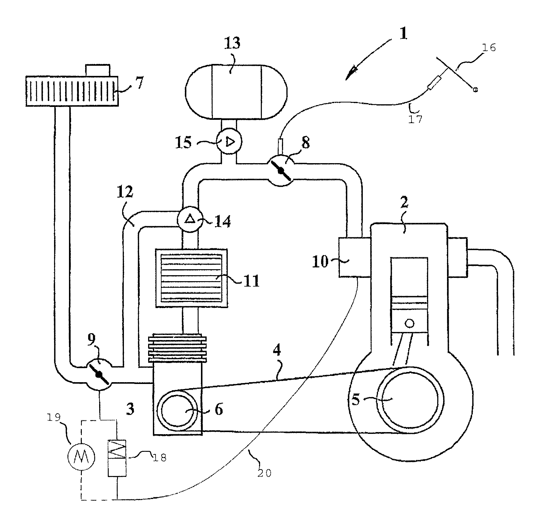
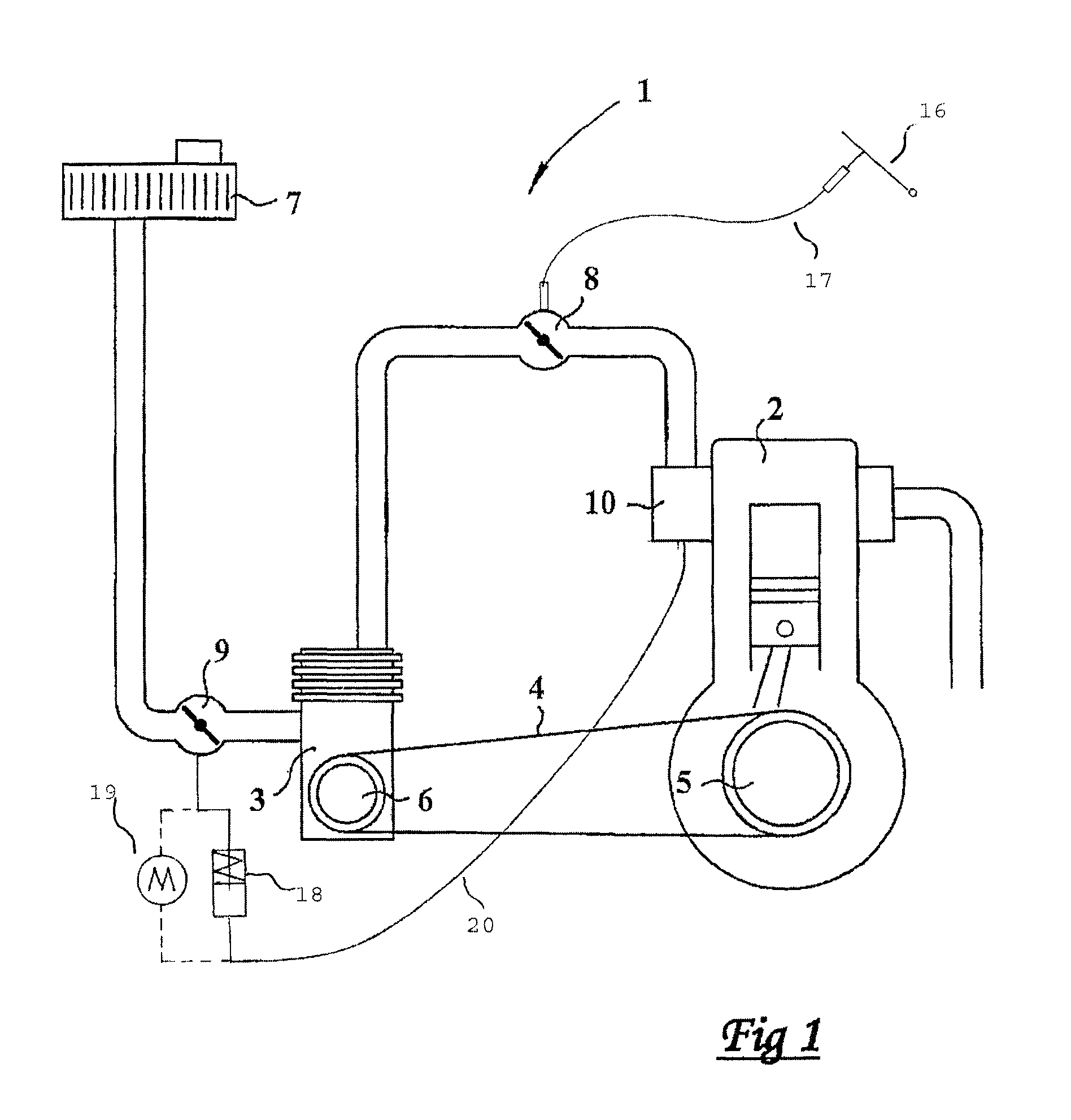
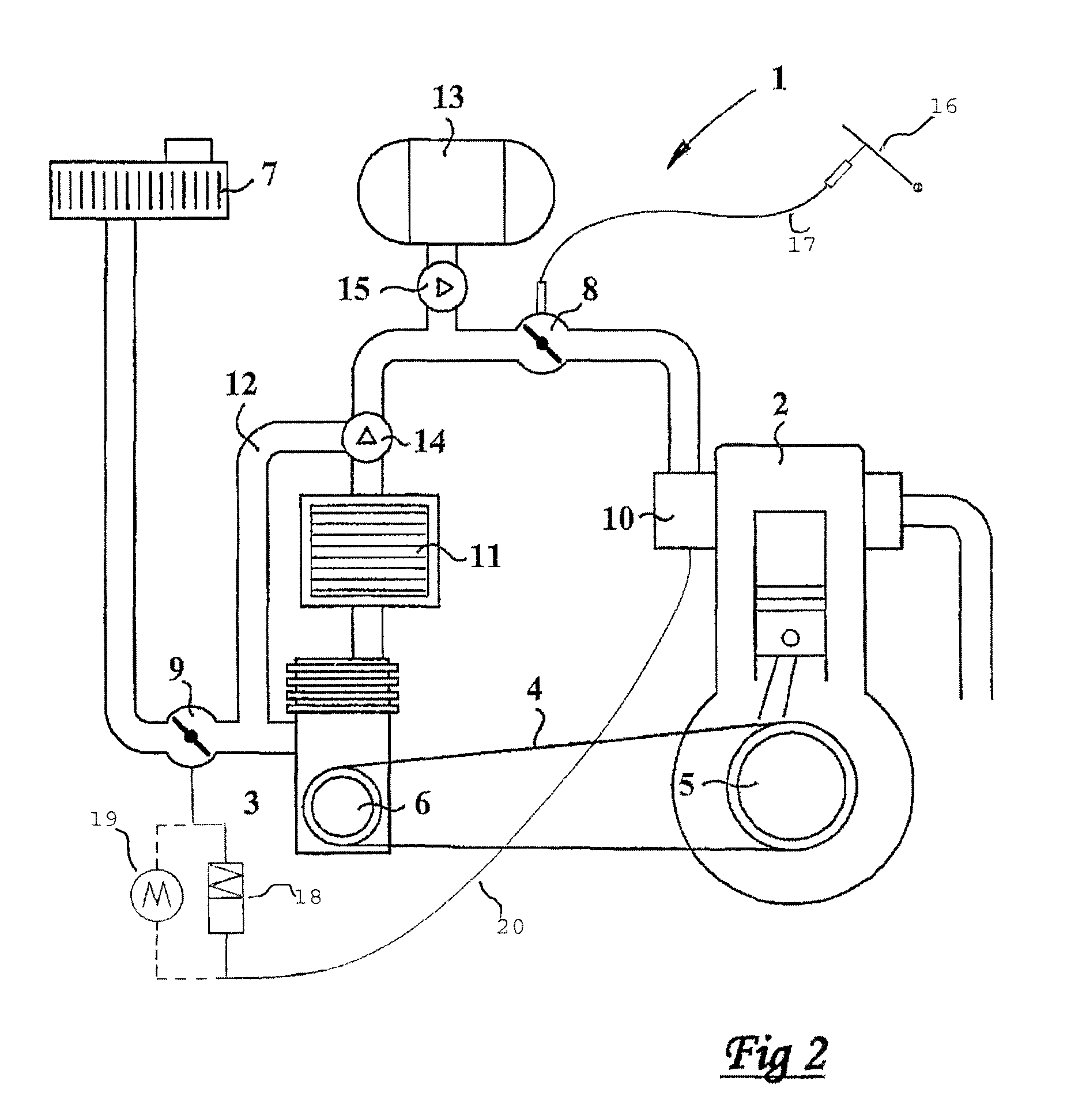
[0015]In FIG. 1, a combustion air supply arrangement is shown in a schematic and stripped way comprising an air intake duct, generally designated 1, connected to a co-operating motor 2, which through said air intake duct 1 receives air for the combustion of fuel in the cylinders of the same. Thus, the motor 2 is an internal combustion engine and, preferably, a petrol-powered one. It should be pointed out that by combustion air supply arrangement, herein reference is made jointly to all the components that co-operate with each other, which are located upstream the cylinders of the engine 2 and which together provide the engine 2 with air, which is intended for the combustion of fuel. That is, the invention may be said to relate to a combustion air supply arrangement that comprises an air intake duct 1 of a combustion chamber of an internal combustion engine 2 as well as a plurality of components arranged in or adjacent to the air intake duct 1. It may also be said to relate to an int...


PUM


Abstract

The invention relates to a combustion air supply arrangement, including an air intake duct of an internal combustion engine, and a compressor arranged in the air intake duct, and a first throttle located downstream the compressor and upstream the internal combustion engine and arranged to change the flow area of the air intake duct between the compressor and the internal combustion engine, the same furthermore including a second throttle, which is located upstream the compressor and which is arranged to change the flow area of the air intake duct upstream the compressor. Furthermore, the compressor is a centrifugal compressor, the rotational speed of which is directly dependent on the rotational speed of the internal combustion engine, and that the combustion air supply arrangement is arranged in such a way that the sucked-in air is compressed once between the second throttle and the internal combustion engine.

Description

TECHNICAL FIELD OF THE INVENTION[0001]This invention relates to a combustion air supply arrangement, comprising an air intake duct of an internal combustion engine, and a compressor arranged in the air intake duct, and a first throttle located downstream the compressor and upstream the internal combustion engine and having the purpose of changing the flow area of the air intake duct between the compressor and the internal combustion engine, the same furthermore comprising a second throttle, which is located upstream the compressor and which is arranged to change the flow area of the air intake duct upstream the compressor.[0002]The throttle has the purpose of shutting off the air supply to the engine when the accelerator control is disengaged, for instance in connection with the change of gearing from the engine. Already here it should be pointed out that by throttle, herein reference is made to all types of valves, air chokes and throttle valves that regulate the throughput of air ...

Claims


Application Information

Patent Timeline
Patent Type & Authority Patents(United States)
IPC IPC(8): F02B33/00F02B33/44F02B21/00F02B29/04F02B33/40F02D9/02F02M
CPCF02B33/40F02B33/446F02D9/02F02B33/44F02B21/00F02B29/0406F02D2009/0272F02B33/00F02D23/005
Inventor KOENIGSEGG, CHRISTIAN V.
Owner KOENIGSEGG AUTOMOTIVE
Why Eureka
Try Eureka