
Infrared gas detection and spectral analysis method

a gas detection and infrared technology, applied in the field of infrared spectroscopy, can solve the problems of contaminated sample interrogated by point sensors, inability to use empirical spectrum that reflects the current state of the sensor, and high false alarm rate of continuous gas detection monitor technology, etc., to achieve the effect of enhancing the threat of chemical detection

Active Publication Date: 2011-06-07
THE AEROSPACE CORPORATION
View PDF8 Cites 11 Cited by
  • Summary
  • Abstract
  • Description
  • Claims
  • Application Information

AI Technical Summary

Benefits of technology

This approach significantly reduces false alarms and enhances sensitivity to threat chemicals by modeling background and interferent spectra as noise, allowing for continuous, accurate detection of threat chemicals in real-time without requiring frequent calibration.

Problems solved by technology

However, there are difficulties associated with implementing the technology in a continuous gas detection monitor system requiring a very low false alarm rate and high sensitivity.
When infrared spectroscopy is used in a continuously monitoring point sensor, the sample interrogated by the point sensor may be contaminated at any time, and contamination could be due to threat chemicals or interferent chemicals.
Furthermore, a contaminant may be present over an extended period of time making it impossible to use an empirical spectrum that reflects the current state of the sensor.
However, clean air injection reduces the duty cycle of the system and requires accurate modeling of atmospheric constituents to accomplish background removal.
The background problem for hyperspectral imaging is even more complicated than the simple infrared spectroscopy case.
Existing infrared spectroscopy systems and methods disadvantageously process threat spectra and interferent spectra identically and different than background spectra.
These systems and methods have disadvantageously used static non-decaying backgrounds for threat detection.
In hyperspectral imaging, the covariance and mean of the background model has been processed in the linear space, which would be disadvantageous for the continuous monitoring case because of the computational burden.
The prior continuous monitoring systems and methods have insufficiently low false alarm rate and insufficiently high sensitivities for many applications.

Method used


Image

  • Infrared gas detection and spectral analysis method
  • Infrared gas detection and spectral analysis method
  • Infrared gas detection and spectral analysis method

Examples


Embodiment Construction

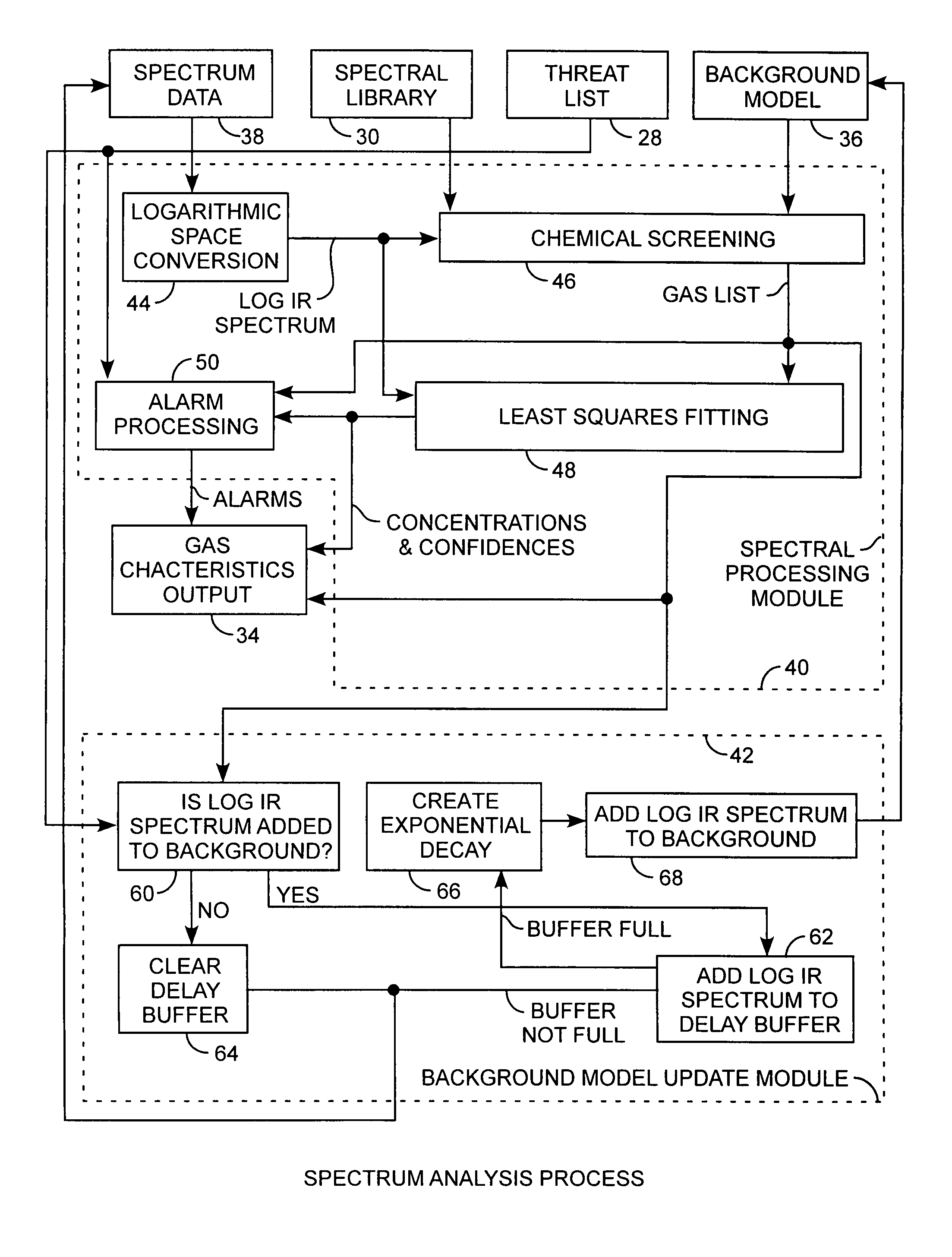
[0021]An embodiment of the invention is described with reference to the figures using reference designations as shown in the figures. Referring to FIG. 1, a gas detection system includes a light source 10 providing white light to a sample cell 12 containing a gas sample from a gas source 14. The gas sample is sourced from the gas source 14, passed through the sample cell 14, and sunk into a gas sink 16. The gas sample attenuates the white light into attenuated light. The attenuated light is passed through a spectral element 18 for translating the attenuated light into dispersed light. The dispersed light is detected by a detector 20 for providing a detector signal to a gas detection processor 22. The gas detection processor 22 converts the detector signal into spectrum data using a signal conversion process 24. The gas detection processor 22 then uses a spectrum analysis process 26 to receive the spectrum data, a spectral library 30, start up conditions 32 of a chemical background, ...


PUM


Abstract

A gas detection system and method for analysis of infrared gas spectra is used for chemical threat detection, quantification and alarm, using a chemical library, a chemical threat list, and a background model that incorporates the data history, allows spectra containing interferent signals into the background model, the model being updated using delay buffering to prevent threat spectra incorporation and using exponential decays to preferentially represent recent background history, all computed in the logarithmic space for rapid detection and alarm.

Description

STATEMENT OF GOVERNMENT INTEREST[0001]The invention was made with Government support under contract No. FA8802-04-C-0001 by the Department of the Air Force. The Government has certain rights in the invention.FIELD OF THE INVENTION[0002]The invention relates to the field of infrared spectroscopy. More particularly, the present invention relates to infrared spectroscopic gas detection.BACKGROUND OF THE INVENTION[0003]Infrared spectroscopy is a relatively rapid, sensitive, and chemically specific technique for the detection of a large variety of chemicals. However, there are difficulties associated with implementing the technology in a continuous gas detection monitor system requiring a very low false alarm rate and high sensitivity.[0004]Infrared spectroscopy is a well-known technique for chemical identification and quantification. The observed infrared signal I is linked to chemical concentration by Beer's Law equation I(ν)=Io (ν)e−ε(ν)cl, where Io is the background signal, ε is the ...

Claims


Application Information

Patent Timeline
Patent Type & Authority Patents(United States)
IPC IPC(8): G08B17/10
CPCG01N21/3504G08B31/00G08B21/12G01N2201/1293
Inventor POLAK, MARK LEONNEALY, CARLTON DOUGLASSTAFSUDD, JOHN P.
Owner THE AEROSPACE CORPORATION
Learn More