
Assist feature placement based on a focus-sensitive cost-covariance field

a technology of cost-covariance and assist feature, applied in the direction of photomechanical equipment, instruments, originals for photomechanical treatment, etc., can solve the problems of inability to accurately determine the placement and/or clean up of assist features, the complexity of such rules increases rapidly, and designers are required to increase the effor

Active Publication Date: 2011-05-31
SYNOPSYS INC
View PDF21 Cites 12 Cited by
  • Summary
  • Abstract
  • Description
  • Claims
  • Application Information

AI Technical Summary

Benefits of technology

This approach enables more accurate and efficient assist feature placement, reducing the need for aggressive clean-up rules and improving semiconductor device performance by minimizing contour movement due to focus changes, thus enhancing the depth of focus and adaptability to new manufacturing processes.

Problems solved by technology

Unfortunately, such rule-based approaches can result in missed or sub-optimal placement and / or clean up of assist features.
Furthermore, the complexity of such rules increases rapidly with shrinking feature size, thereby requiring increasing effort on the part of designers.
Moreover, these rules can be overly restrictive, which can prevent designers from achieving optimal semiconductor device performance.
However, because this placement technique for the contact hole layers is based on maximizing intensity at the center of contacts, the technique often produces incorrect AF placement solutions when it is applied to line-space layers.
Unfortunately, ILT-based AF placement techniques not only require many iterations to converge on a solution but often produce poor AF placement results.

Method used


Image

  • Assist feature placement based on a focus-sensitive cost-covariance field
  • Assist feature placement based on a focus-sensitive cost-covariance field
  • Assist feature placement based on a focus-sensitive cost-covariance field

Examples


Embodiment Construction

[0037]The following description is presented to enable any person skilled in the art to make and use the invention, and is provided in the context of a particular application and its requirements. Various modifications to the disclosed embodiments will be readily apparent to those skilled in the art, and the general principles defined herein may be applied to other embodiments and applications without departing from the spirit and scope of the present invention. Thus, the present invention is not limited to the embodiments shown, but is to be accorded the widest scope consistent with the claims.

[0038]The data structures and code described in this detailed description are typically stored on a computer-readable storage medium, which may be any device or medium that can store code and / or data for use by a computer system. This includes, but is not limited to, volatile memory, non-volatile memory, magnetic and optical storage devices such as disk drives, magnetic tape, CDs (compact dis...


PUM


Abstract

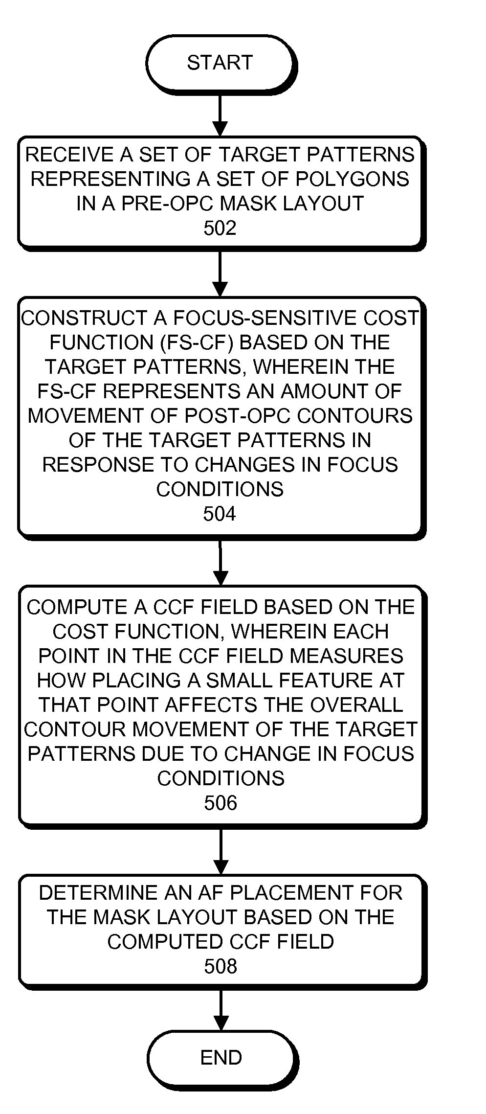
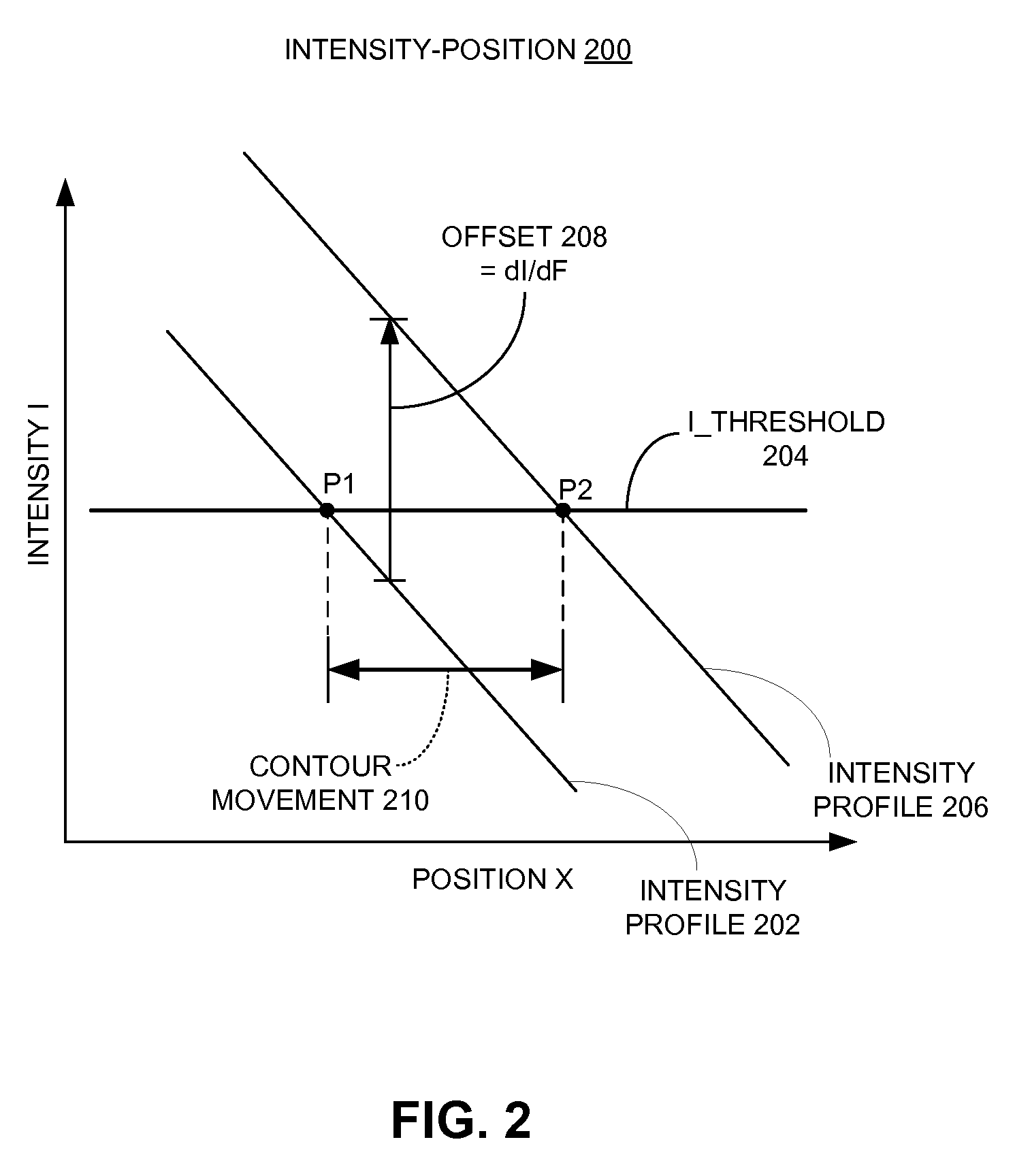
One embodiment of the present invention provides a system that determines an assist feature placement within a post-optical proximity correction (post-OPC) mask layout. During operation, the system receives a set of target patterns which represent a set of polygons in a pre-OPC mask layout. The system then constructs a focus-sensitive cost function based on the target patterns, wherein the focus-sensitive cost function represents an amount of movement of post-OPC contours of the target patterns in response to changes in focus condition of the lithography system. Note that the contours of the target patterns substantially coincide with the edges of set of the polygons. Next, the system computes a cost-covariance field (CCF field) based on the focus-sensitive cost function, wherein the CCF field is a two-dimensional (2D) map representing changes to the focus-sensitive cost function due to an addition of a pattern at a given location within the post-OPC mask layout. Finally, the system generates assist features for the post-OPC mask layout based on the CCF field.

Description

BACKGROUND[0001]1. Field of the Invention[0002]Embodiments of the present invention generally relate to techniques for designing and manufacturing integrated circuits (ICs). More specifically, embodiments of the present invention relate to a technique for determining assist feature placement in a mask layout based on a focus-sensitive cost-covariance field.[0003]2. Related Art[0004]The dramatic improvements in semiconductor integration densities in recent years have largely been made possible by corresponding improvements in semiconductor manufacturing technologies.[0005]One such manufacturing technology involves placing assist features in a mask layout to improve the depth of focus of the patterns on the mask layout which are intended to be printed on the wafer. Such assist features can be printing assist features (e.g., super-resolution assist features) or non-printing assist features (e.g., sub-resolution assist features).[0006]Existing techniques for placing assist features typi...

Claims


Application Information

Patent Timeline
Patent Type & Authority Patents(United States)
IPC IPC(8): G06F17/50
CPCG03F1/36G03F1/70G03F7/70641G03F7/70441G03F7/705G03F7/70433
Inventor BARNES, LEVI D.PAINTER, BENJAMIN D.YAN, QILIANGFAN, YONGFALI, JIANLIANGPOONAWALA, AMYN
Owner SYNOPSYS INC
Learn More