
Wheel-embedded suspension

a technology of suspension and wheel, applied in the direction of electric propulsion mounting, electric devices, transportation and packaging, etc., can solve the problems of increasing the unsprung and rotational mass, affecting safety and handling, and the conventional suspension used to support the combined hub and motor assembly uses space very inefficiently, so as to simplify the car design, facilitate the effect of speeding up and reducing the weigh

Inactive Publication Date: 2011-05-10
MASSACHUSETTS INST OF TECH
View PDF9 Cites 40 Cited by
  • Summary
  • Abstract
  • Description
  • Claims
  • Application Information

AI Technical Summary

Benefits of technology

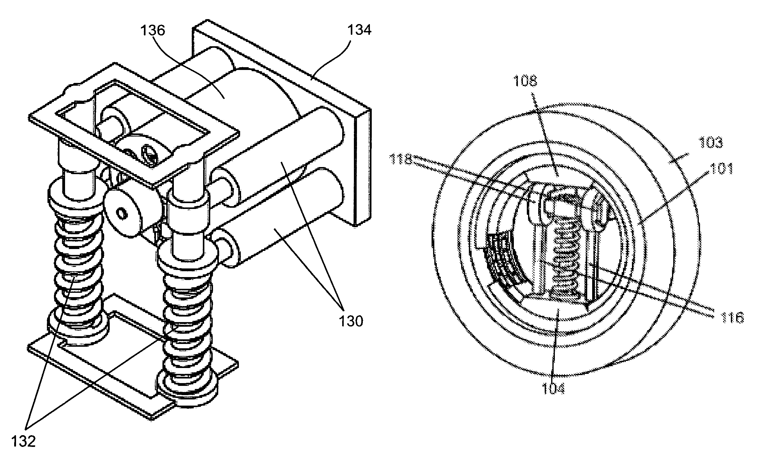
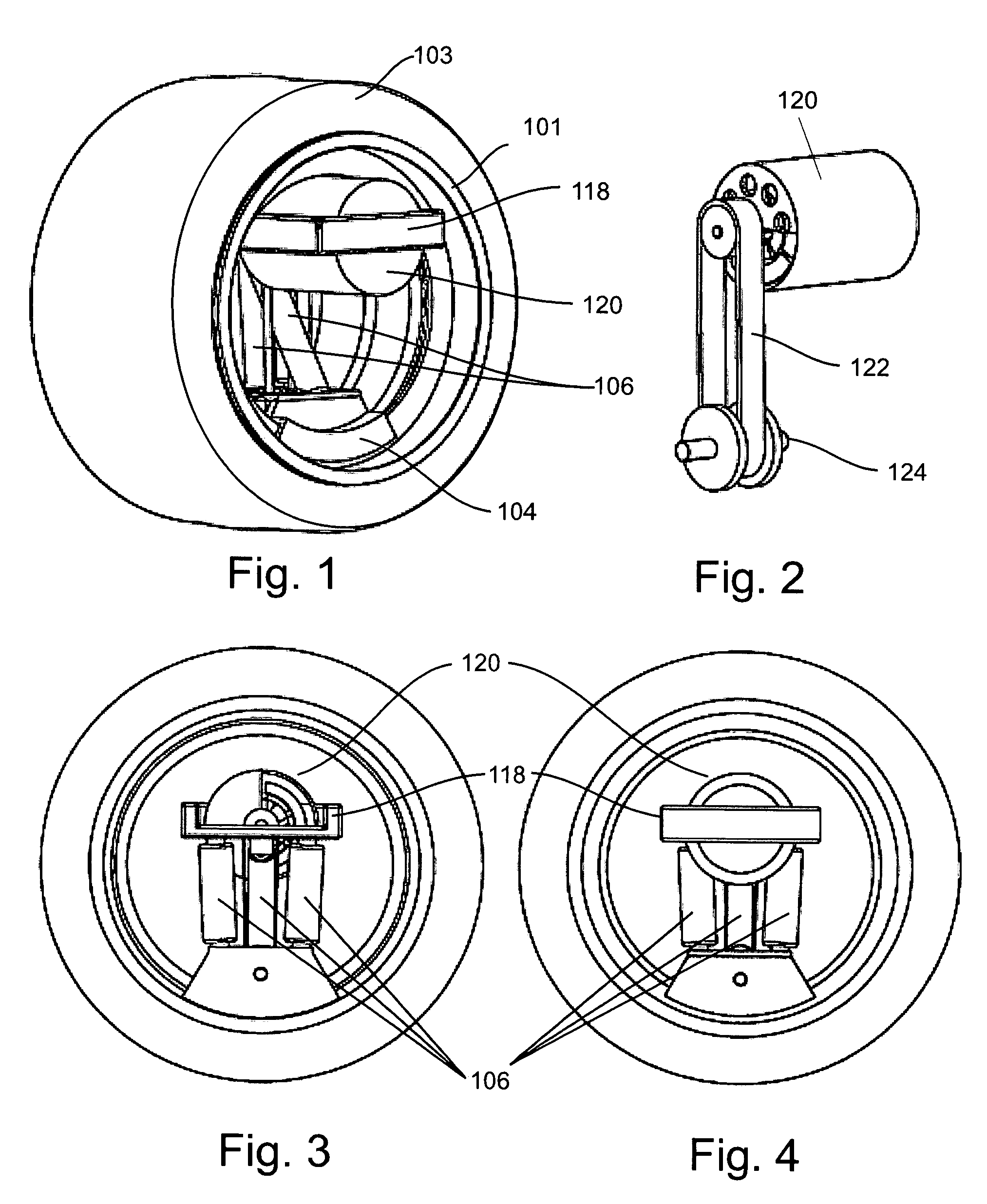
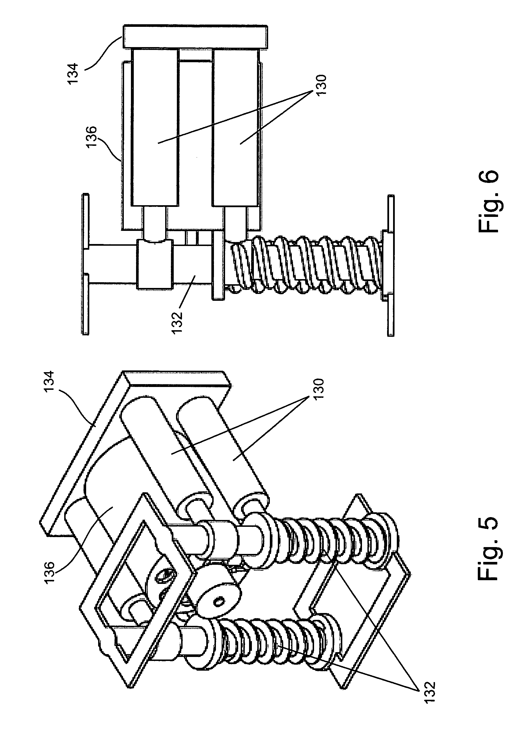
[0005]The present invention may be used to advantage to implement a self-contained, single-wheel, electric motor drive and suspension system that can be independently controlled. Such a self-contained “wheel robot” can incorporate every component needed to drive, steer, suspend and lean a car wheel as required in an automobile or other vehicle. Attached to a chassis with a minimal number of connection points, these self-contained wheel robots only require electrical power and driving data to propel a vehicle. The availability of such a self-contained wheel robot can radically simplify car design, especially chassis design and engineering which become much easier, faster and cheaper because the chassis no longer houses components such as the motor, drive shaft and gear box.

Problems solved by technology

There are normally significant disadvantages that flow from attaching the motor to the wheel hub.
The resulting dramatic increase in unsprung and rotational mass both adversely affect safety and handling.
Moreover, the conventional suspension used to support the combined hub and motor assembly uses space very inefficiently.
Because hub-mounted electrical motors add significant unsprung and rotational mass to a suspension, compromising handling and safety, and because motors mounted outside the hub increase the already large requirements of traditional suspensions for space and complicate production, there is a need for an improved suspension and drive mechanism for use with a wheel driven by an electric motor.

Method used


Image

  • Wheel-embedded suspension
  • Wheel-embedded suspension
  • Wheel-embedded suspension

Examples


second embodiment

[0072]A second embodiment described in connection with FIGS. 23-29 employs a triangular shaft 201 that transmits power from the motor to the wheel 200 from an electric motor (not shown) transmits power to the shaft 201 via a gear assembly 203 that is rotated by a motor drive gear 202 seen in FIG. 25. The bearing assembly houses three bearings (seen at 205 in FIG. 25) which make contact with the triangular shaft 201, allowing little play between the bearing assembly 203 and the shaft 201 so that power may be transmitted, but allowing the shaft 201 to rotate with the bearing assembly 203 about the shaft axis, and also allowing the shaft 201 to move longitudinally along the axis of the triangular shaft 201. In this way, the shaft 201 can travel along its longitudinal axis relative to gear assembly 203, and hence relative to the motor and chassis, as the wheel rim 204 moves up and down. One or both ends of the triangular shaft 201 form a gear as seen at 206 in FIG. 23 that engages with ...

third embodiment

[0077]A third embodiment shown in FIG. 30 employs three drive gears 303, 305 and 306 arranged in a triangular formation so that one gear 303 (the motor gear) is driven by the motor and transmits power to a middle gear 305 which in turn transmits power to a third gear 306 (the rim gear) which is in constant contact with and engages the crown gear 309 attached to the rim. The angle between the links 311 and 313 which support the gears, and therefore the distance between the motor gear 303 and the rim gear 306, is variable, allowing the gears to be continuously engaged and deliver power during up and down travel of the wheel 315. The motor gear is rigidly attached to the sprung frame member 320 that is supported by the springs 322.

[0078]Off-center Traveling Suspension Axis

fourth embodiment

[0079]As more components are added to the hub or the unsprung portions of the suspension, unsprung mass increases. The arrangements described above suspend the tire and the rim in a way that allows maximum suspension travel while keeping all other components (motor, drive-force transmission, steering, suspension and activators) inside the wheel stable and consequently sprung. The fourth embodiment shown in FIGS. 31 and 32 employ an off-center suspension traveling axis indicated along the dashed line 403 as shown in FIG. 31. The axis 403 sitting near the rim and outside the wheel center axis 405 allows the wheel to travel up and down as the support arm 407 pivots about the off-center axis 403. The advantage of this wheel suspension design is that the suspension axis can easily be used to drive the wheel directly or function as the drive force transmission axis. As seen in FIG. 31, the shaft of the drive motor 411 drives the belt 413 which is coupled to a drive shaft that rotates abou...


PUM


Abstract

An in-the-wheel suspension system including a drive mechanism for coupling the rotational motion of a wheel rim to the drive shaft of an electric motor and for supporting the wheel rim with respect to the vehicle chassis using one or more springs and dampers. In a hubless version, a spring member supports extend between a frame member attached to the chassis and a bearing member that engages with the rim. In a version used with a wheel hub, the hub is supported by an axle and the spring member supports the axle in movable relation to the frame member. A pivoting support arm that is attached to the axel and pivots about a pivot point attached to the frame member at a location spaced from the wheel axis may be used to support the hub. A Peaucellier linkage may be used to support the axle for movement along a straight line vertical path, the linkage being attached to the frame member at two fixed pivot points. The wheel suspension units perform all the traditional drivetrain functions independently and can be attached to the chassis in a manner that allows for easy removal.

Description

Cross Reference to Related Application[0001]This application is a Non-Provisional of, and claims the benefit of the filing date of, U.S. Provisional Patent Application Ser. No. 60 / 579,972 filed on Jun. 15, 2004 by Patrik Alwin Künzler entitled “Wheel-Embedded Suspension.”FIELD OF THE INVENTION[0002]This invention relates to vehicle suspension and drive systems.BACKGROUND OF THE INVENTION[0003]Placing an electric motor on the hub of a motor vehicle results in space savings and better efficiency in power transmission when compared to other motor placements. There are normally significant disadvantages that flow from attaching the motor to the wheel hub. The resulting dramatic increase in unsprung and rotational mass both adversely affect safety and handling. Moreover, the conventional suspension used to support the combined hub and motor assembly uses space very inefficiently.[0004]Because hub-mounted electrical motors add significant unsprung and rotational mass to a suspension, comp...

Claims


Application Information

Patent Timeline
Patent Type & Authority Patents(United States)
IPC IPC(8): B60K17/14B62D7/18B60G9/00
CPCB60G3/01B60G17/0195B60G2200/10B60G2200/422B60K7/0007B60G2204/4191B60G2204/4193B60G2206/011B60G2300/50B60G2204/30B60L2220/44B60L2220/50Y02T10/64
Inventor KUNZLER, PATRIK ALWINSCHMITT, PETERPOBLANO, RAUL-DAVID V.CHAN, BRIANLIANG, PHILIP A.VAIRANI, FRANCO H.KILIAN, AXELCHIN, RYAN CMITCHELL, WILLIAM J.
Owner MASSACHUSETTS INST OF TECH
Learn More