Stent tissue graft prosthesis

Active Publication Date: 2011-03-29
OREGON HEALTH & SCI UNIV +2
View PDF11 Cites 23 Cited by
  • Summary
  • Abstract
  • Description
  • Claims
  • Application Information

AI Technical Summary

Benefits of technology

[0013]The foregoing problems are solved and a technical advance is achieved in an illustrative embodiment of a stent and tissue graft prosthesis in which a tissue graft is disposed on a first or inner expandable stent and an outer tubular member such as a second or outer expandable stent is disposed over the tissue graft and around the first expandable stent for retaining advantageously the tissue graft disposed on the inner stent. As a consequence, holes through the tissue graft are advantageously minimized, if not eliminated, and the probability of endoleaks are significantly lessened. In this preferred illustrative embodiment, the ends of the inner and outer stent along with that of the tissue graft are advantageously aligned to coincide with each other. This alignment further advantageously allows host tissue coming in contact with the tissue graft to remodel and become incorporated into the prosthesis when the tissue graft includes, for example, an extracellular matrix material (ECM) such as small intestine submucosa.
[0014]Other embodiments of the present invention include extending the inner expandable stent beyond the end of the tissue graft. However, the outer tubular member is still positioned at least entirely over the tissue graft or extends beyond the ends of the tissue graft so as to advantageously prevent undesirable eversion or displacement of the tissue graft during, for example, placement of the prosthesis and, in particular, when withdrawing a delivery catheter from the prosthesis. Keeping the ends of the inner expandable stent coincident with the ends of the tissue graft prevents the tissue graft from everting or folding into the passage of the inner expandable stent. As a result, the tissue graft is prevented from narrowing the passage or lumen of the vessel and / or creating an edge, shelf, and the like for thrombus and the like to build up on or adhere to. Since the stent tissue graft prosthesis is typically placed in an arterial vessel, pulsatile blood flow can cause the eversion of the tissue graft over either end of the inner expandable stent, which is advantageously prevented when the ends of the inner expandable stent are coincident with or extend beyond the ends of the tissue graft.
[0015]The outer tubular member of the tissue stent graft prosthesis can advantageously assume one of several different configurations. In one embodiment, the tubular member includes a perforated tube or sleeve of a polymer material such as polyethyleneteraphalate (PET). The size of the perforations is advantageously selected so as to promote contact with and remodeling of the host vessel tissue therethrough. In the preferred embodiment of the stent tissue graft prosthesis, the tubular member includes a second or outer expandable stent, which can be self-expanding, balloon expandable, or a combination of both. Furthermore, the inner expandable stent can also be self-expanding, balloon expandable, or a combination of both. In the preferred embodiment, the inner and outer expandable stents each include a plurality of circumferential segments and a plurality of tie bars longitudinal interconnecting the circumferential segments. The circumferential segments advantageously include a serpentine configuration and preferably a zigzag pattern of generally straight struts interconnected by a plurality of bends. The zigzag pattern advantageously provides for a compressed stent diameter, which facilitates loading into a delivery system for delivering the prosthesis to an implantation site. When released, the zigzag pattern can typically expand six or more times its compressed diameter to bring the tissue graft between the inner and outer expandable stents in contact with the vessel wall.

Problems solved by technology

Abrupt transitions between the stented and unstented portions can cause significant trauma and undesirable intimal hyperplasia with consequent narrowing of the vessel.
This consequence is typically referred to as “edge effect.” Attachment sutures or other attachment configurations allow for a leakage of blood through the covering material, thus producing undesirable and / or life-threatening endoleaks.
This eversion creates a significant problem in that the aneurysm is no longer excluded and in that the stent graft with its everted tissue material presents a significant problem in its removal.

Method used


Image

  • Stent tissue graft prosthesis
  • Stent tissue graft prosthesis
  • Stent tissue graft prosthesis

Examples


Embodiment Construction

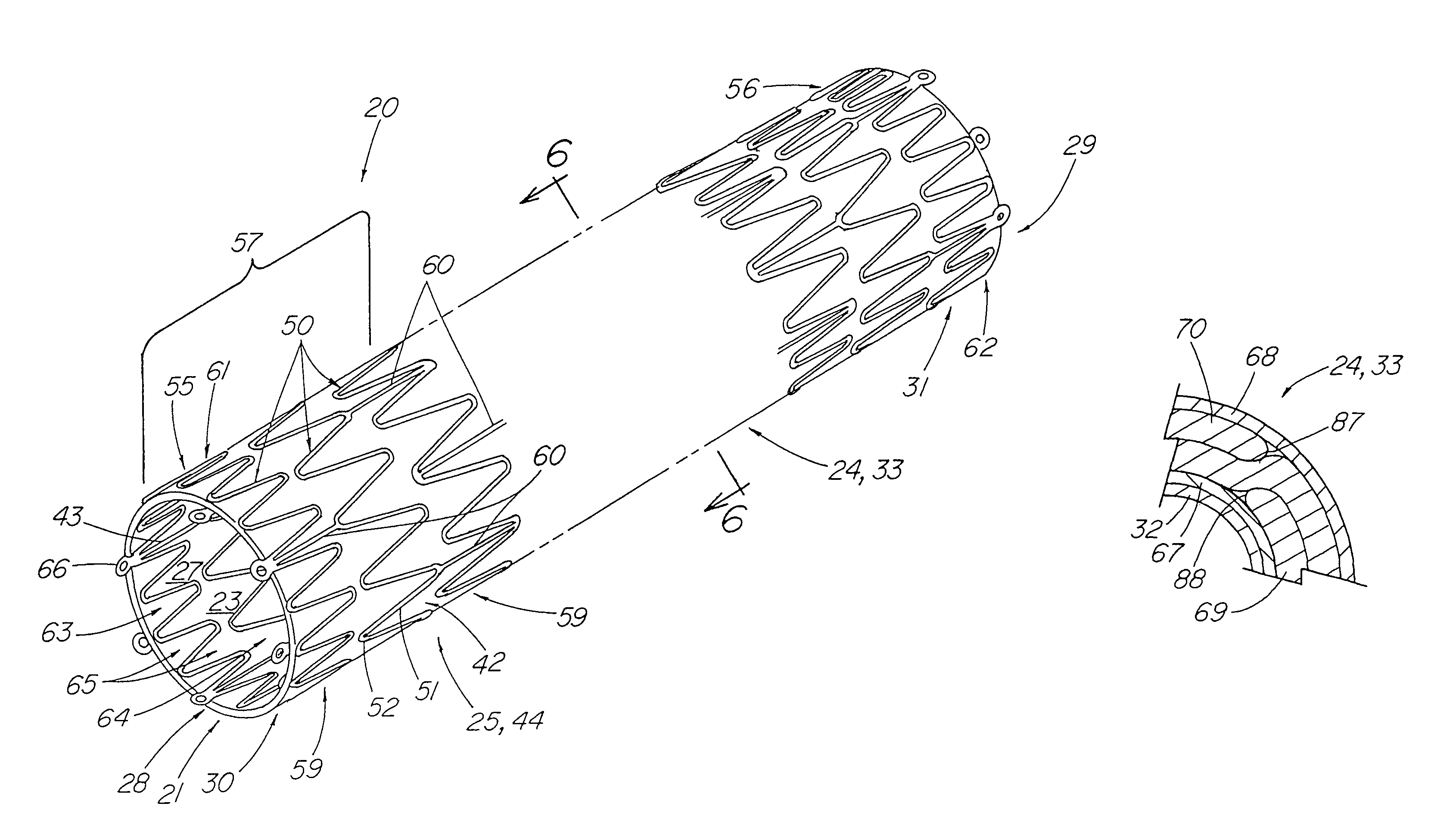
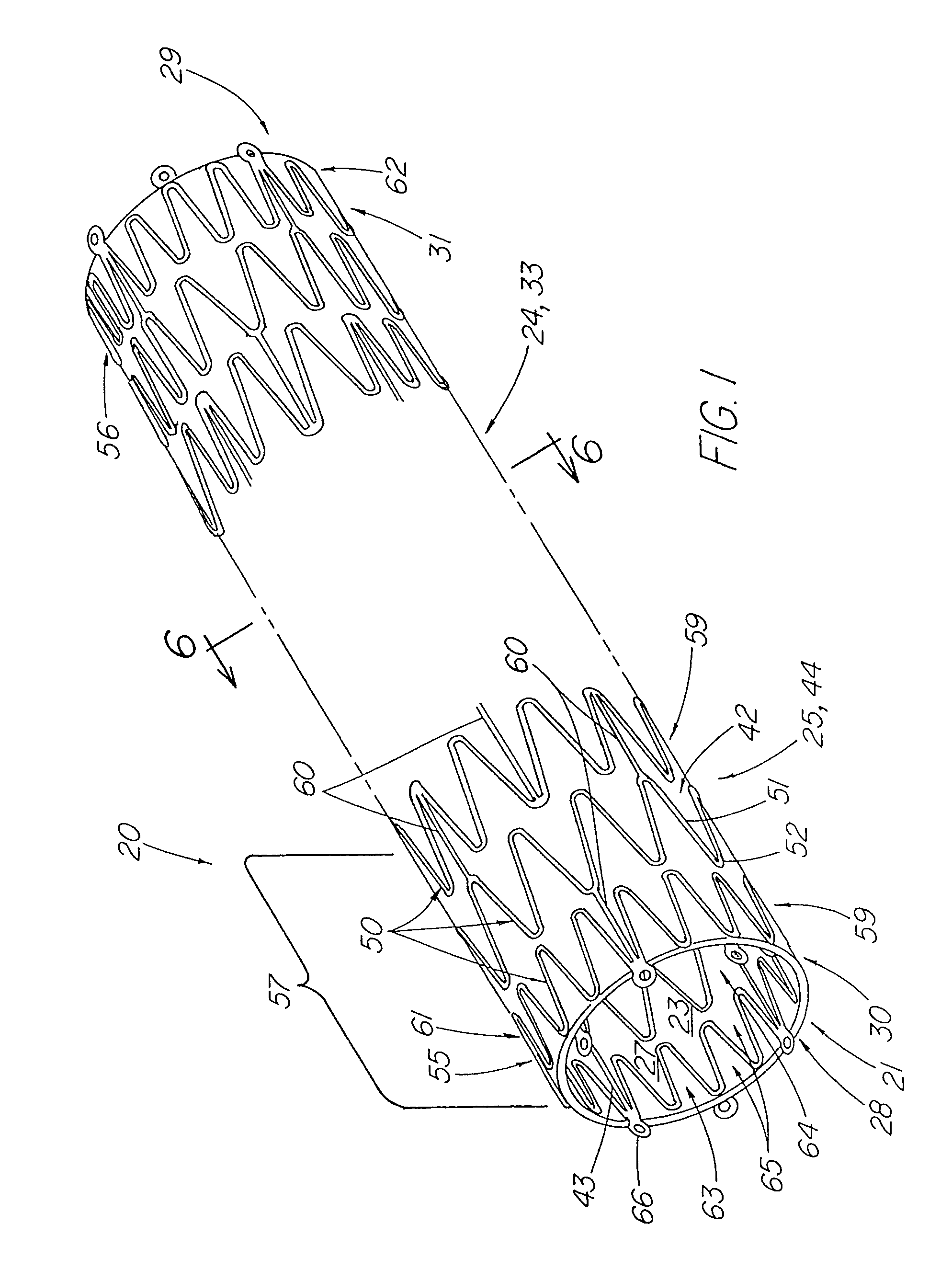
[0037]FIG. 1 depicts a pictorial view of a preferred illustrative embodiment of stent tissue graft prosthesis 20 of the present invention. In addition, this preferred embodiment depicts the best mode of the present invention. Stent tissue graft prosthesis 20 includes a first or inner expandable stent 21 having a passage 23 extending longitudinally therethrough, a tissue graft 24 disposed on inner stent 21 and a tubular member 25 such as a second or outer expandable stent 44 with a passage 27 extending longitudinally therethrough and disposed over the tissue graft and around the inner expandable stent so as to advantageously retain the tissue graft disposed on the first inner stent. The first or inner expandable stent has a distal inner stent end 28 and a proximal stent end 29. Similarly, tissue graft 24 has a distal graft end 30 and a proximal graft end 31. In like fashion, tubular member 25 and, in particular, outer expandable stent 44 includes distal tubular or outer stent end 55 ...


PUM


Abstract

A stent tissue graft prosthesis (20) for repairing, excluding and / or reinforcing a vessel, duct and the like in a patient. The prosthesis includes an inner expandable stent (21) of which a tissue graft (24) and preferably a multilayered tissue construct (33) is disposed thereon for application to the host tissue of a vessel, duct and the like. The tissue construct includes an extracellular matrix material (36) such as small intestine submucosa (37) for remodeling the host tissue into the prosthesis. The prosthesis further includes an outer tubular member (25) such as an outer expandable stent (44) for retaining the tissue graft on the inner stent. The ends of the inner and outer stents are coincident with or extend beyond the ends of the tissue graft to prevent eversion or fold back of the tissue graft during withdrawal of a delivery catheter in a placement procedure.

Description

CROSS-REFERENCE TO RELATED APPLICATIONS[0001]This application claims priority of provisional application Ser. No. 60 / 428,640, filed Nov. 22, 2002.TECHNICAL FIELD[0002]This invention relates generally to medical devices and, in particular, to a stent and tissue graft prosthesis and to a delivery system for delivering the prosthesis to an implantation site such as, for example, an aneurysm in the vascular system of a human or animal patient.BACKGROUND OF THE INVENTION[0003]As background, submucosa tissues have been suggested and used as tissue graft materials. For example, U.S. Pat. No. 2,127,903 to Bowen describes various tubes for surgical purposes which may be constructed of the submucosa layer of animal intestinal tissue. Bowen teaches constructing the tubes using a multiplicity of tissue ribbons or threads which are wound over a tubular form and dried.[0004]U.S. Pat. No. 3,562,820 to Braun describes the use of submucosa or serosa tissues to form prosthesis devices. In one embodim...

Claims


Application Information

Patent Timeline
IPC IPC(8): A61F2/06A61F2/00
CPCA61F2/07A61L27/3629A61L27/3633A61F2/852A61F2/91A61F2/95A61F2002/065A61F2230/0054A61F2/89A61F2002/075A61F2250/0063
Inventor PAVCNIK, DUSANFETTE, CLAY D.MEAD, JASON A.OBERMILLER, JOSEPH F.PARKER, FRED T.
Owner OREGON HEALTH & SCI UNIV
Why Eureka
Try Eureka