Electrical connector with adjacent terminals bent outward

a technology of electrical connectors and adjacent terminals, applied in the direction of coupling device details, coupling device connections, electric discharge lamps, etc., can solve the problems of not meeting consumers' demand and taking more than ten minutes, and achieve the effect of reducing the distance between the two second terminals

Inactive Publication Date: 2011-03-29
I O INTERCONNECT LTD
View PDF5 Cites 2 Cited by
  • Summary
  • Abstract
  • Description
  • Claims
  • Application Information

AI Technical Summary

Benefits of technology

[0008]The present invention relates to an electrical connector with a USB 2.0 interface and a USB 3.0 interface. At least two of the second terminals located at the two sides of the USB 3.0 interface are bent outwardly at a predetermined angle, so that cross talk between two of the second terminals can be reduced.
[0009]The present invention also relates to an electrical connector, wherein the thickness of the solder portion is 1.20 millimeter, so that the cross talk between the second terminals located at two sides of the solder portion can be reduced.
[0010]The present invention provides an electrical connector. The electrical connector includes an insulating body, a plurality of first terminals, a plurality of second terminals and a shielding shell. One end of a base disposed on the insulating body has a first solder portion and a second solder portion, and another end of the base has a connection portion. The first terminals run through the base. The first terminals are arranged parallel to each other and located on two sides of the first solder portion and the connection portion. The second terminals run through the base. The second terminals are located on two sides of the second solder portion and the connection portion. At least two of the second terminals located on the two sides of the second solder portion are bent outwardly at a predetermined angle, so as to increase a distance between two adjacent second terminals and reduce cross talk between the two adjacent second terminals. The shielding shell sleeves on the connection portion and is used for reducing electromagnetic interference between the first terminals and the second terminals.

Problems solved by technology

However, with the development of multimedia technology, it takes more than ten minutes if a multimedia file of 25 GB is downloaded with the USB 2.0 protocol and that may not satisfy consumers' demand.

Method used


Image

  • Electrical connector with adjacent terminals bent outward
  • Electrical connector with adjacent terminals bent outward
  • Electrical connector with adjacent terminals bent outward

Examples


Embodiment Construction

[0019]It is to be understood that other embodiment may be utilized and structural changes may be made without departing from the scope of the present invention. Also, it is to be understood that the phraseology and terminology used herein are for the purpose of description and should not be regarded as limiting. The use of “including,”“comprising,” or “having” and variations thereof herein is meant to encompass the items listed thereafter and equivalents thereof as well as additional items. Unless limited otherwise, the terms “connected,”“coupled,” and “mounted,” and variations thereof herein are used broadly and encompass direct and indirect connections, couplings, and mountings.

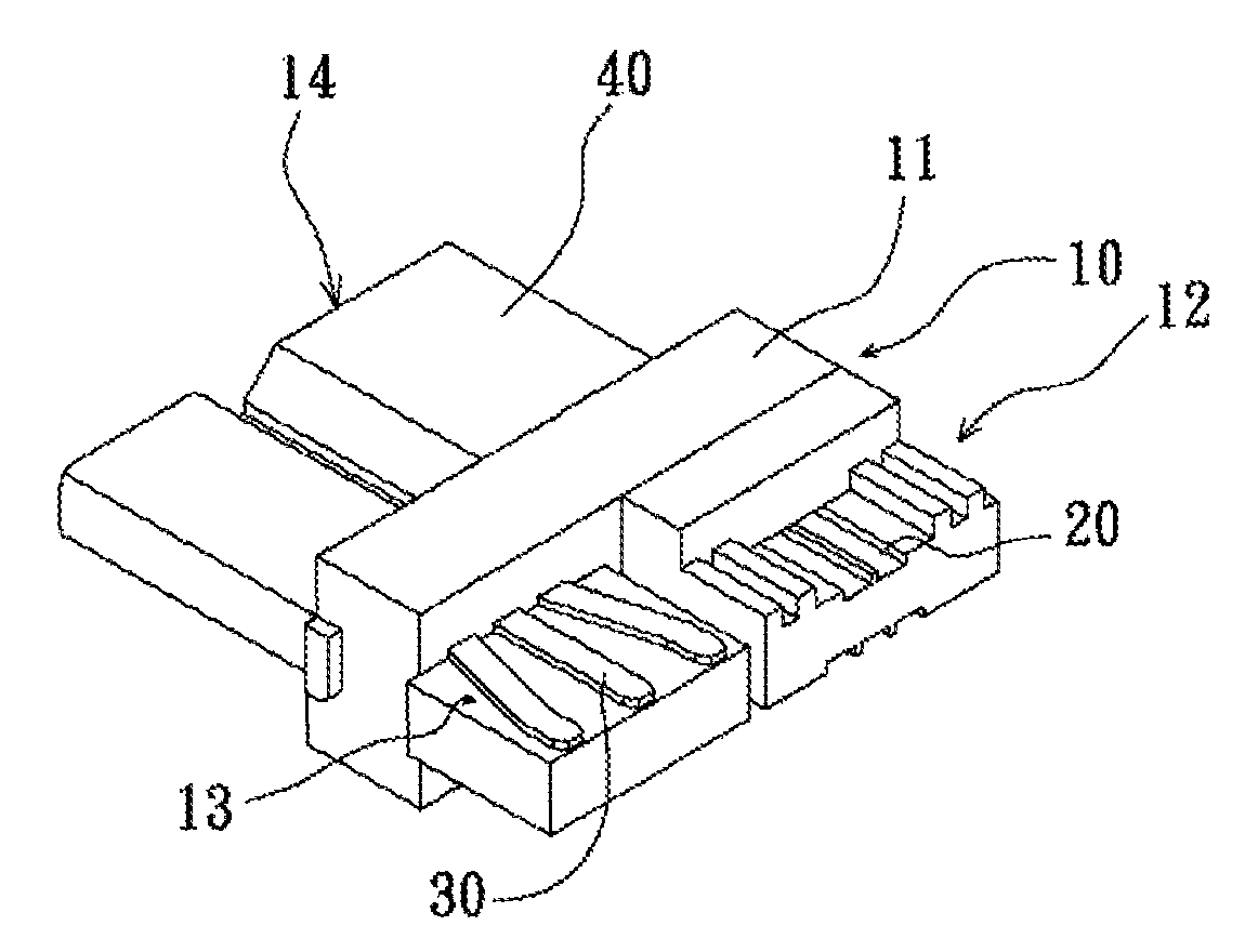
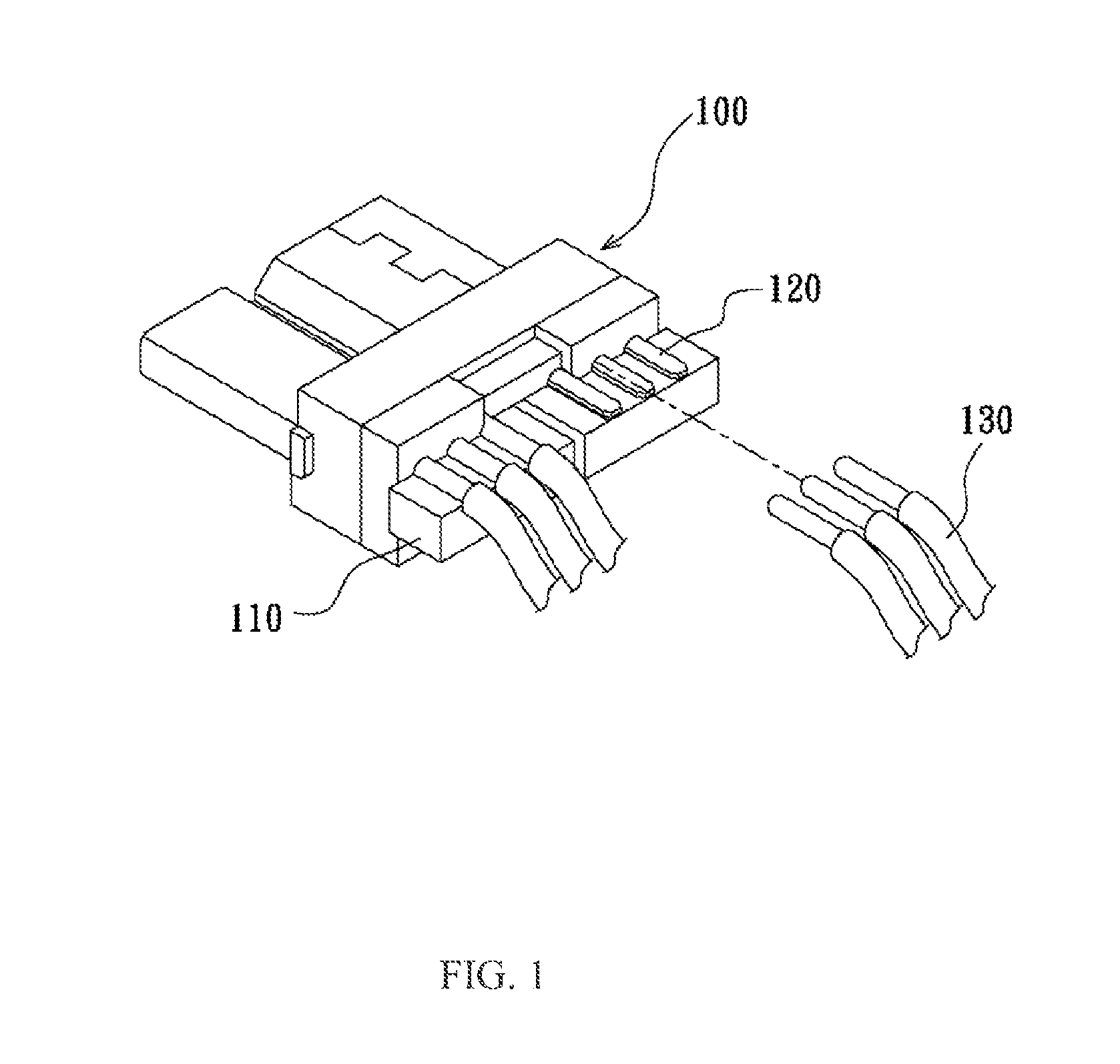
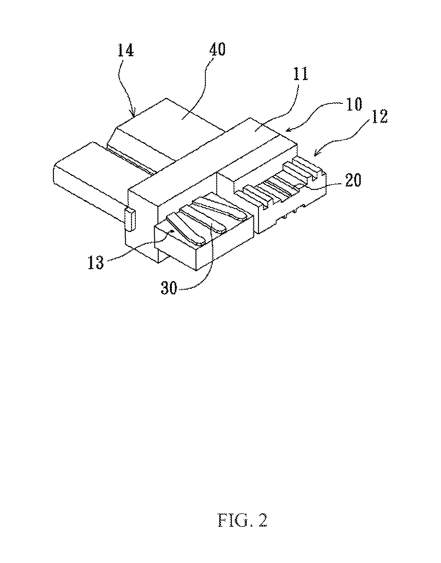
[0020]FIG. 2 is a schematic view of an electrical connector according to an embodiment of the present invention. FIG. 3a is a top view of the electrical connector according to an embodiment of the present invention. FIG. 3b is a bottom view of the electrical connector according to an embodiment of the prese...


PUM


Abstract

An electrical connector includes an insulating body, a plurality of first terminals, a plurality of second terminals and a shielding shell. A base on the insulating body includes a first solder portion, a second solder portion and a connection portion. The first solder portion and the second solder portion are located on the one end of the base, and the connection portion is located on the other end of the base. The first terminals run through the base, and are arranged parallel to each other and located on two sides of the first soldering portion and the connection portion. The second terminals run through the base, and are separately located on two sides of the second soldering portion and the connection portion. At least two of the second terminals are bent outwardly at a predetermined angle, so that the cross talk between two adjacent second terminals can be reduced. The shielding shell sleeves on the connection portion. Additionally, the thicknesses of the first solder portion and the second solder portion both are 1.20 mm so that the cross talk of the second terminals located at the two sides of the second solder portion can be reduced.

Description

CROSS-REFERENCE TO RELATED APPLICATION[0001]This application claims the priority benefit of Taiwan application serial no. 098223744, filed on Dec 18, 2009. The entirety of the above-mentioned patent application is incorporated herein by reference and made a part of this specification.BACKGROUND[0002]1. Technical Field[0003]The present invention relates to an electrical connector, and more particularly to an electrical connector with a USB 2.0 interface and a USB 3.0 interface. At least two of the second terminals located at two sides of the USB 3.0 interface are bent outwardly at a predetermined angle, so that cross talk between adjacent two second terminals can be reduced.[0004]2. Description of the Related Art[0005]Currently, due to the plug and play function, peripheral devices with USB interfaces become popular. A data transfer rate provided by the USB 2.0 protocol may be as high as 480 Mbit / s. However, with the development of multimedia technology, it takes more than ten minute...

Claims


Application Information

Patent Timeline
Patent Type & Authority Patents(United States)
IPC IPC(8): H01R24/00H01R33/00
CPCH01R9/03H01R13/6585H01R13/6461H01R13/6581H01R27/02H01R4/023
Inventor LI, SHOU-SHENGJIANG, SHUN-GUO
Owner I O INTERCONNECT LTD
Why Eureka
Try Eureka