
Magnetic detection coil and apparatus for measurement of magnetic field

a magnetic detection coil and magnetic field technology, applied in the field of biomagnetism measurement apparatus, can solve the problems of inability to adequately reduce an effect, inevitably accompanied by a reduction in the detection of magnetic signals, and the effect of reducing an effect is not easy to achieve, so as to avoid a decrease in the detection sensitivity of magnetic signals, increase the s/n ratio, and reduce the

Inactive Publication Date: 2011-03-22
HITACHI HIGH-TECH CORP
View PDF16 Cites 21 Cited by
  • Summary
  • Abstract
  • Description
  • Claims
  • Application Information

AI Technical Summary

Benefits of technology

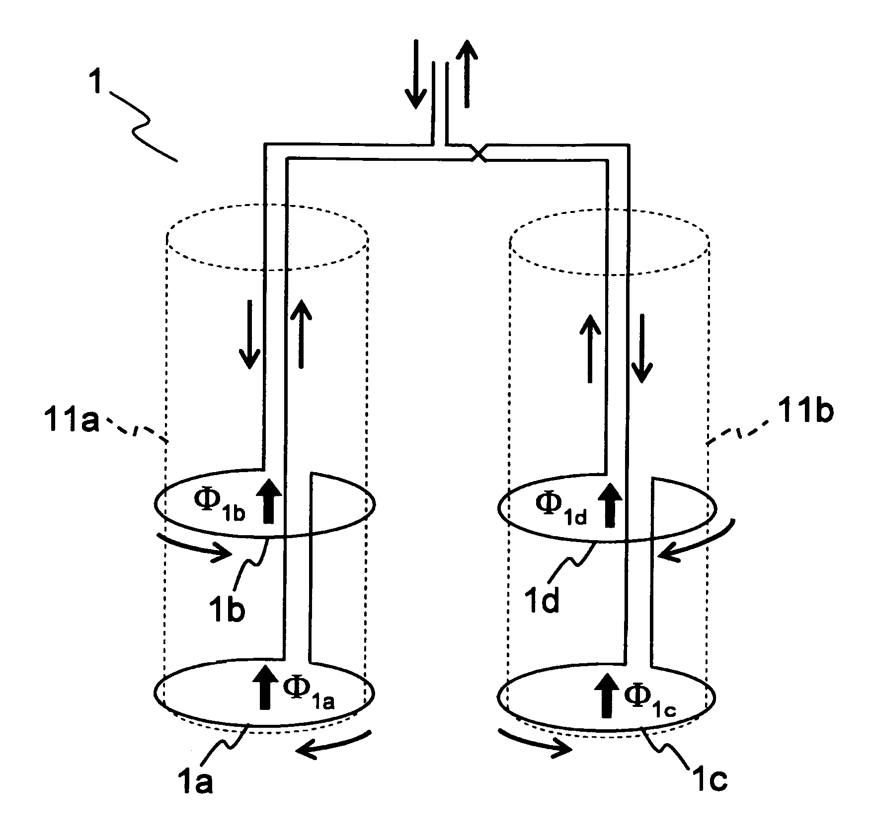
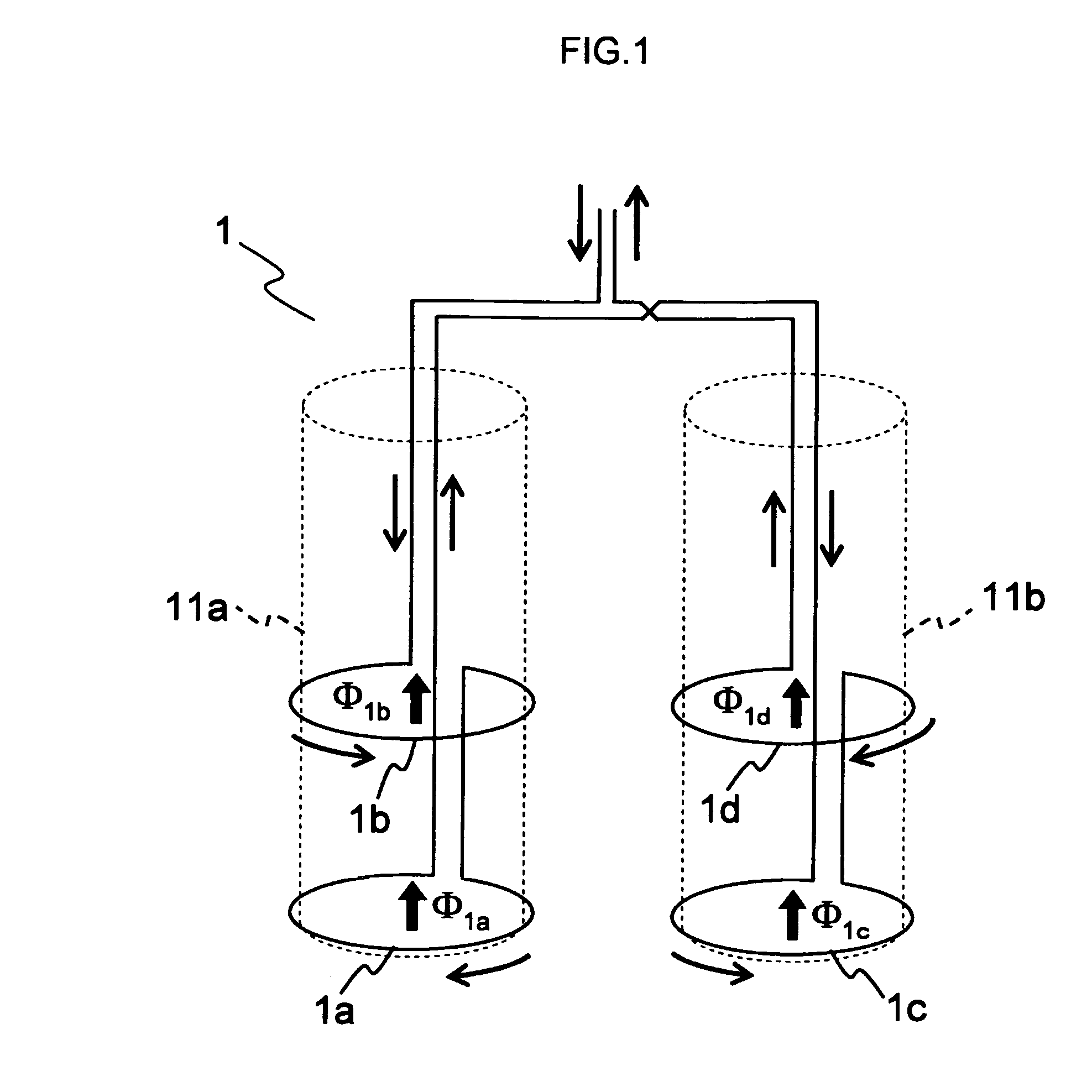
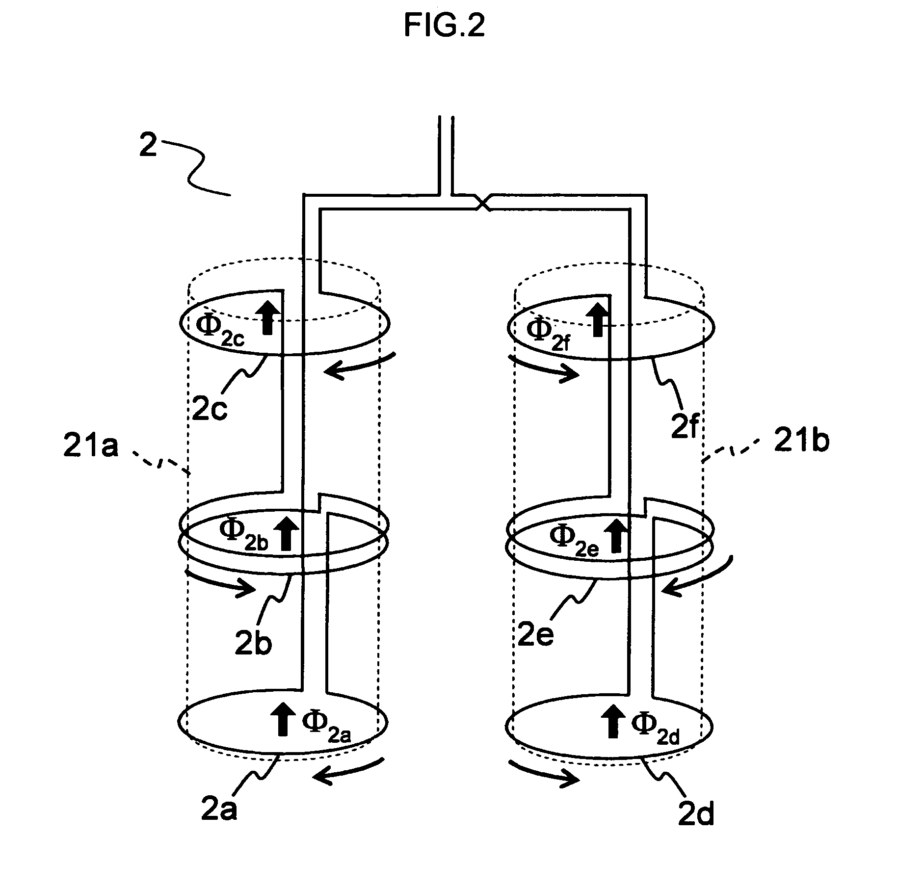
The present invention provides a magnetic detection coil and an apparatus for measuring a magnetic field that have increased signal-to-noise ratios (S / N ratios) as a result of not only maintaining sensitivity for magnetic signals but also reducing the effect of environmental magnetic fields. This is achieved by using a plurality of differential coils made of superconductor and metallic materials arranged in parallel at spatially predetermined intervals and mutually electrically connected. Each differential coil is a first-order and a second-order differential coil.

Problems solved by technology

However, the zero-order differential magnetic detection coil does not decrease an effect of environmental magnetic fields at all, directly experiencing noise due to the environmental magnetic fields.
These arrangements have a problem that when environmental magnetic fields are strong because a magnetically shielded room is not available, for example, it is not possible to adequately reduce an effect of them.
Although the effect can be decreased by this technique, it is inevitably accompanied by a reduction in a magnetic signal to be detected.
A magnetic detection coil using a superconducting thin film has a problem that it is intrinsically difficult to form a coil three-dimensionally.
In addition, it appears to be unproductive to combine these two types of coils, because magnetic detection coils with three-dimensional structure as shown in FIGS. 18A to 18C and magnetic detection coils formed on a superconducting thin film as shown in FIGS. 18D and 18E are different from each other in terms of usage, structure and manufacturing processes.

Method used


Image

  • Magnetic detection coil and apparatus for measurement of magnetic field
  • Magnetic detection coil and apparatus for measurement of magnetic field
  • Magnetic detection coil and apparatus for measurement of magnetic field

Examples


Embodiment Construction

[0050]An embodiment of the present invention is now described in detail with reference to the drawings. In the drawings referenced hereinafter, items having a same function are given a same reference number.

[0051]Low-temperature superconducting materials or high-temperature superconducting materials can be used as superconducting materials for a magnetic detection coil used in an apparatus described in the following embodiment. A low-temperature superconducting material, which has a low superconductor transition temperature, works as a superconductor in a low-temperature (liquid helium temperature) environment. In contrast, a high-temperature superconducting material, which has a high superconductor transition temperature, works as a superconductor in a high-temperature (liquid nitrogen temperature) environment. It may be possible to alternatively adopt a superconducting material having a superconductor transition temperature between the liquid helium temperature and the liquid nitr...


PUM


Abstract

A magnetic detection coil is provided, which includes a plurality of differential coils. Each differential coil is made of one of superconductors and metallic materials. The differential coils having mutually different loop directions are arranged in parallel at a spatially predetermined distance apart and mutually electrically connected in series. Each differential coil is one of a first-order differential coil and a second-order differential coil.

Description

CLAIM OF PRIORITY[0001]The present application claims priority on Japanese application JP2005-300991 filed on Oct. 14, 2005, the content of which is hereby incorporated by reference into this application.BACKGROUND OF THE INVENTION[0002]The present invention relates to an apparatus for measurement of biomagnetism which employs magnetic detection coils and superconducting quantum interference devices.[0003]An apparatus for measurement of biomagnetism, which is used for magnetocardiography and magnetoencephalography, has so far employed a technique that a magnetic detection coil made of superconducting wires detects magnetic signals generated by an organism to transmit to a superconducting quantum interference device (hereinafter referred to as SQUID). A SQUID has a superconductor ring with a Josephson junction, in which a voltage between both ends of the Josephson junction cyclically varies with a period of Φ0=h / 2e (Wb) according to a magnetic flux penetrating the SQUID.[0004]It has ...

Claims


Application Information

Patent Timeline
Patent Type & Authority Patents(United States)
IPC IPC(8): A61B5/00
CPCG01R33/02G01R33/0358A61B5/242
Inventor SEKI, YUSUKEKANDORI, AKIHIKO
Owner HITACHI HIGH-TECH CORP
Learn More