Terahertz wave detection device, camera, imaging device, and measuring device
a detection device and terahertz wave technology, applied in the field of terahertz wave detection devices, camera, imaging devices, measuring devices, can solve the problems of noise and decrease of detection sensitivity with respect to terahertz wave, and achieve the effect of suppressing the reduction of detection sensitivity due to electric nois
- Summary
- Abstract
- Description
- Claims
- Application Information
AI Technical Summary
Benefits of technology
Problems solved by technology
Method used
Image
Examples
second embodiment
3.1 Second Embodiment
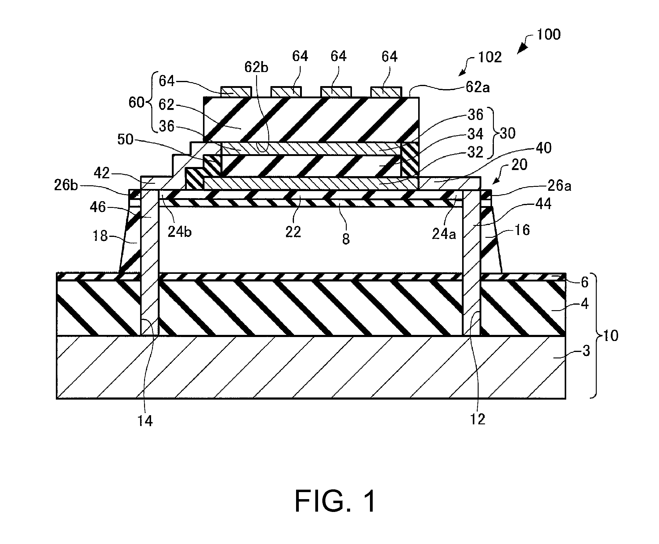
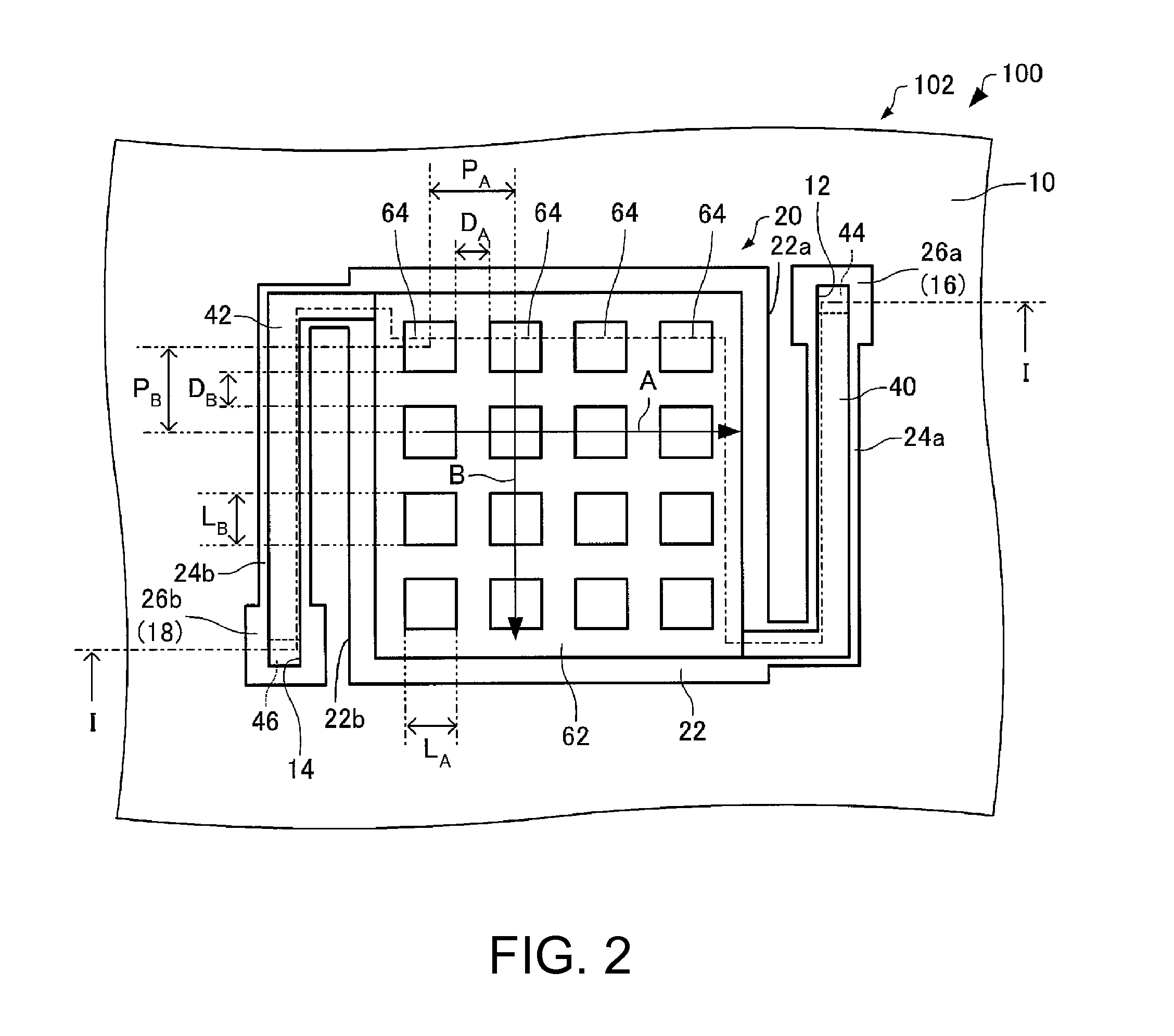
[0123]Next, a terahertz wave detection device according to a first modification example, or second embodiment will be described with reference to the drawings. FIG. 13 is a plan view schematically showing a terahertz wave detection device 200 according to the first modification as is shown in the second embodiment, and corresponds to FIG. 2.
[0124]Hereinafter, in the terahertz wave detection device 200 according to the second embodiment, the same reference numerals are attached to members having the same functions as the component members of the terahertz wave detection device 100 according to the first embodiment, and the detailed descriptions thereof are omitted. This is also applied similarly to a terahertz wave detection device 200 according to a third embodiment described below.
[0125]As shown in FIG. 2, in the terahertz wave detection device 100, the metal structures 64 have square planar shapes. In contrast, as shown in FIG. 13, in the terahertz wave detect...
third embodiment
3.2 Third Embodiment
[0127]Next, a terahertz wave detection device according to a third embodiment will be described with reference to the drawings. FIG. 14 is a plan view schematically showing a terahertz wave detection device 300 according to the third embodiment, and corresponds to FIG. 2.
[0128]As shown in FIG. 2, in the terahertz wave detection device 100, the metal structures 64 have square planar shapes. In contrast, as shown in FIG. 14, in the terahertz wave detection device 300, the metal structures 64 have equilateral triangular planar shapes.
[0129]According to the terahertz wave detection device 300, similar to the terahertz wave detection device 100, the detection device can have high detection sensitivity.
fourth embodiment
3.3 Fourth Embodiment
[0130]Next, a terahertz wave detection device according to a fourth embodiment will be described with reference to the drawings. FIGS. 15 to 17 are plan views schematically showing metal structures 64 of the terahertz wave detection device according to the fourth embodiment. Hereinafter, in the terahertz wave detection device according to the fourth embodiment, components which differ from the example of the terahertz wave detection device 100 according to the embodiment will be described, and the descriptions of similar points will be omitted.
[0131]As shown in FIG. 2, in the terahertz wave detection device 100, the metal structures 64 have square planar shapes. However, the metal structures 64 are not limited thereto, and as shown in FIGS. 15 to 17, may have various planar shapes.
[0132]The metal structures 64 shown in FIG. 15 have planar shapes of 2m-fold symmetry (here, m≧2). Compared to the terahertz wave detection device including metal structures 64 shown i...
PUM
 Abstract
Description
Claims
Application Information
 - R&D
- Intellectual Property
- Life Sciences
- Materials
- Tech Scout
- Unparalleled Data Quality
- Higher Quality Content
- 60% Fewer Hallucinations
Browse by: Latest US Patents, China's latest patents, Technical Efficacy Thesaurus, Application Domain, Technology Topic, Popular Technical Reports.
© 2025 PatSnap. All rights reserved.Legal|Privacy policy|Modern Slavery Act Transparency Statement|Sitemap|About US| Contact US: help@patsnap.com


