
Reducing orientation directivity and improving operating distance of magnetic sensor coils in a magnetic field

Inactive Publication Date: 2003-04-24
MICROCHIP TECH INC
View PDF0 Cites 21 Cited by
  • Summary
  • Abstract
  • Description
  • Claims
  • Application Information

AI Technical Summary

Benefits of technology

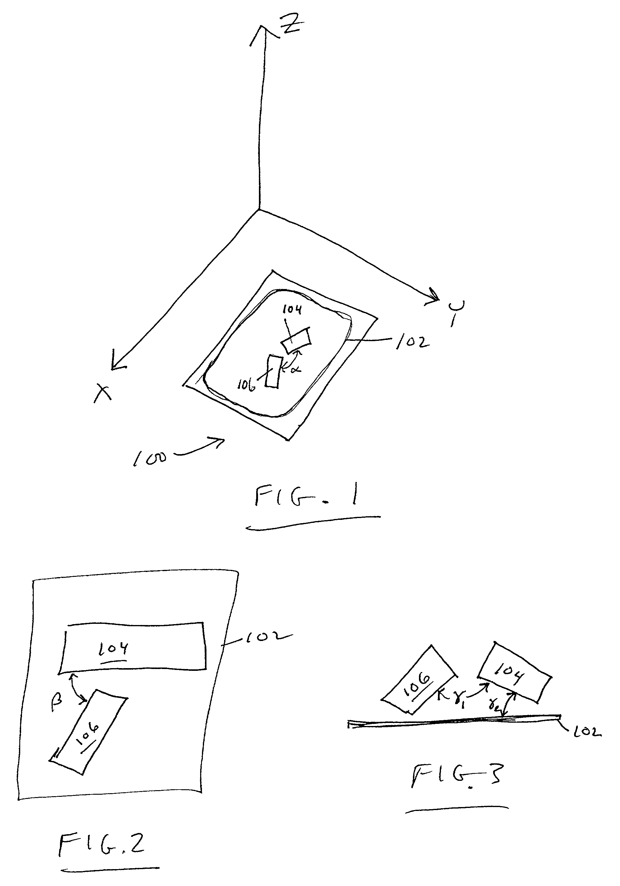
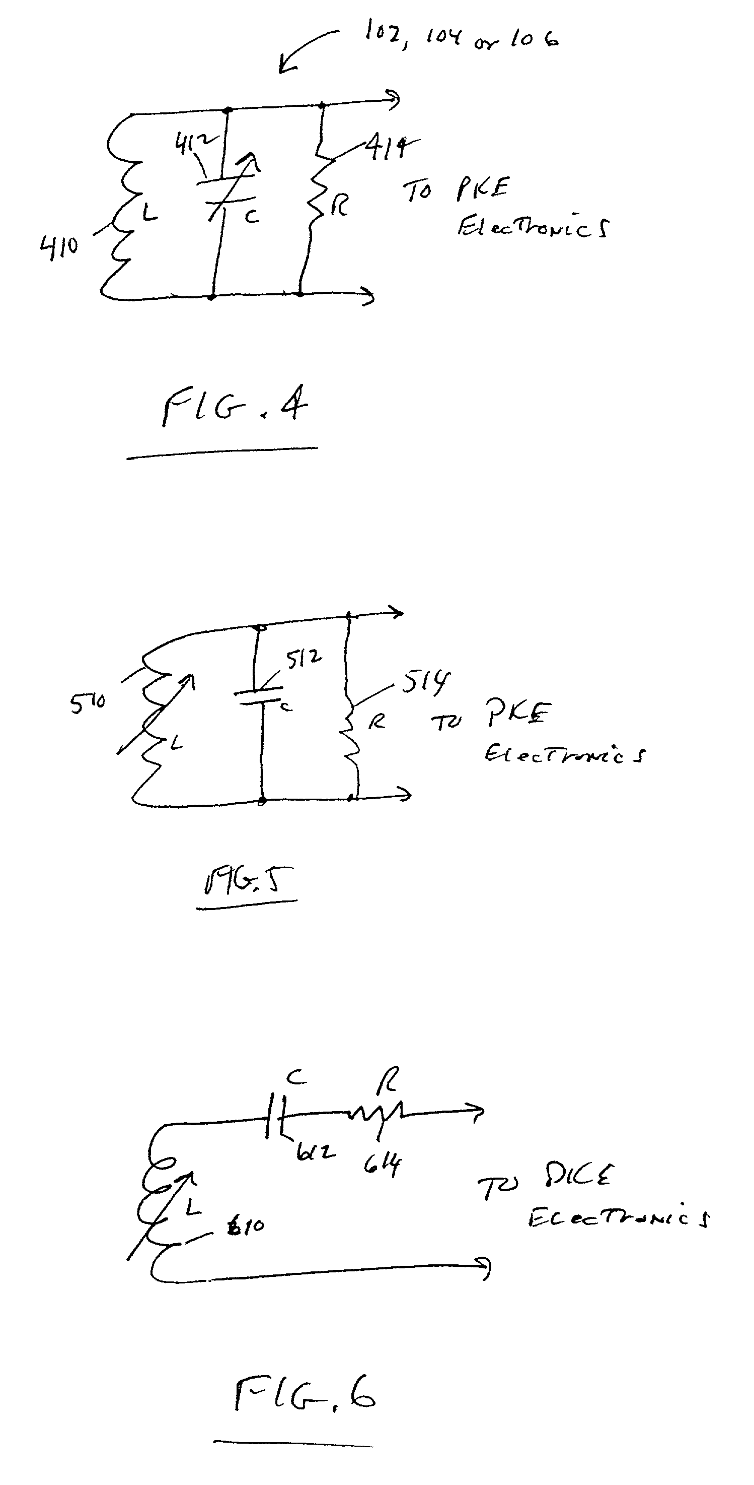
[0016] In another exemplary embodiment of a PKE key-fob, according to the present invention, a plurality of magnetic field sensor coils are arranged in various positional arrangements within the key-fob, e.g., perpendicular, non-perpendicular, parallel, non-parallel, etc. One or more of the plurality of magnetic field coils may be a substantially flat coil of conductive turns where the coil turns are predominantly toward the outside perimeter of the area enclosed by the coil and the conductive turns are insulated from each other. The other ones of the plurality of magnetic field sensor coils may each comprise a plurality of conductive turns, insulated from each other, and wound over a core material of high magnetic permeability, e.g., ferrite, iron, etc., that increases the inductance value of the coil so that the coil may be physically smaller in size than an air wound coil equivalent. In the alternative, all of the plurality of magnetic field sensor coils may be compact sensor coils having windings on a high permeability core. Each of the plurality of magnetic field sensor coils may be resonant at a different frequency so that detection sensitivity of the magnetic field by the sensor coils is maximized for all positional orientations of the PKE key-fob. Stagger tuning of the sensor coils to slightly different frequencies but near the frequency of the interrogator thereby reduces interaction between the coils that may reduce the detection sensitivity over some of the position orientations of the PKE key-fob.
[0018] A technical advantage of the present invention is improved read range at all positional orientations of the PKE key-fob. Another technical advantage is increased sensitivity of the magnetic sensors due to a reduction of detuning effects from mutual inductance coupling between coils.

Problems solved by technology

A problem arises, however, when the magnetic sensor coils must be shrunk in size to fit into a relatively small key-fob.
This close proximity of magnetic sensor coils with other components causes a distortion in the magnetic field lines around the sensor coils.
Any of these influences may cause a shift in the resonant frequency of one or both sensor coils away from the desired resonant frequency when sensing the interrogator magnetic field, thus resulting in a loss of sensitivity that affects the read range of the PKE system.
However, directly electrically exciting a pick-up coil does not take into account the magnetic environment and influences surrounding and proximate to the pick-up coil sensor being tuned.
Accurate testing and measurement equipment is also extremely expensive when trying to directly electrically tune the pickup coil.

Method used


Image

  • Reducing orientation directivity and improving operating distance of magnetic sensor coils in a magnetic field
  • Reducing orientation directivity and improving operating distance of magnetic sensor coils in a magnetic field
  • Reducing orientation directivity and improving operating distance of magnetic sensor coils in a magnetic field

Examples


Embodiment Construction

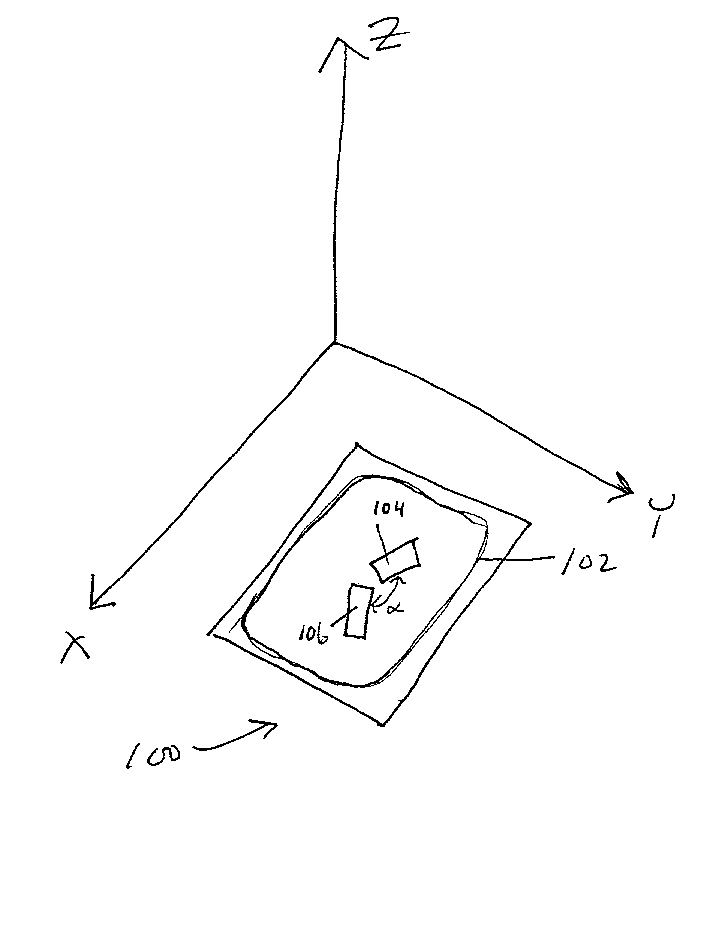
[0027] Referring now to the drawings, the details of an exemplary specific embodiment of the invention is schematically illustrated. FIG. 1 illustrates a schematic isometric diagram of magnetic sensor coil orientations, according to specific exemplary embodiments of the present invention. Three dimensional space is represented by X, Y and Z vectors. A PKE key-fob, generally represented by the numeral 100, has magnetic field sensor coils 102, 104 and 106. More or less sensor coils may be utilized in the present invention and are contemplated herein. The sensor coils 102, 104 and 106 may be any type of coil normally used for PKE system applications. The sensor coils 102, 104 and 106 may all have high magnetic permeability cores over which coils of wire are wound so as to create a physically small a coil, or one or more of the coils may be formed in substantially a plane of two dimensions and having a plurality of turns of wire located along the perimeter of the plane, e.g., coil 102. ...


PUM


Abstract

In a passive keyless entry (PKE) system, a PKE key-fob has magnetic sensor coils arranged in non-perpendicular and non-parallel orientations therebetween, resulting in a more uniform omnidirectional pickup pattern when sensing a time varying magnetic field source from an interrogator base station of the PKE system. The magnetic sensor coils may also be stagger tuned to reduce frequency resonance change due to mutual inductance coupling interaction and / or create a desired magnetic field frequency response pickup pattern. Reducing null zones of different orientations of the PKE key-fob results in more uniform and reliable operation of the PKE system, and tuning the magnetic sensors to operate within the correct frequency and bandwidth of the interrogation magnetic signal increases the useful operating range of the PKE key-fob.

Description

[0001] This application is related to co-pending patent applications Ser. Nos. ______ [attorney docket number 068354.1169 / MTI-1869 / 1870], entitled "Apparatus and Method of Increasing the Sensitivity of Magnetic Sensors Used in Inductively Coupled Magnetic Field Transmission and Detection Systems," filed ______, by Ruan Lourens, Steven Dawson and Pieter Schieke, and U.S. Ser. No. ______ [attorney docket number 068354.1178 / MTI-1891.US.0], entitled "Tuning of Sensor Resonant Frequency in a Magnetic Field," filed Oct. 18, 2001, by Ruan Lourens, Paul Forton and Michel Sonnabend, both applications are hereby incorporated by reference herein for all purposes.[0002] The present invention relates generally to inductively coupled magnetic field transmission and detection systems, such as passive keyless entry (PKE) systems, and more particularly to an apparatus and method for improving orientation and operating distance of magnetic sensors employed in such systems.BACKGROUND OF THE INVENTION ...

Claims


Application Information

Patent Timeline
IPC IPC(8): G07C9/00H01Q1/32
CPCG07C9/00309H01Q1/3241G07C2009/00777
Inventor LOURENS, RUANSTEVEN, DAWSONPIETER, SCHIEKE
Owner MICROCHIP TECH INC
Learn More