
Sound focusing mechanism and method of estimating acoustic leakage of an object and method of estimating transmission loss of an object

a technology of acoustic leakage and focusing mechanism, which is applied in the direction of distance measurement, instruments, specific gravity measurement, etc., can solve the problems of difficult to determine the location of acoustic leakage and not always produce the desired effect, and achieve the effect of reducing leakag

Active Publication Date: 2011-03-22
NOISEOUT
View PDF15 Cites 6 Cited by
  • Summary
  • Abstract
  • Description
  • Claims
  • Application Information

AI Technical Summary

Benefits of technology

[0011]Applicants have also developed an innovative method of locating acoustic leakage points along an object. Once acoustic leakage points have been identified, it is possible to propose measures including but not limited to additional layers of sound insulating material for reducing leakage, or acoustically sealing a compromise in an acoustic installation, such as a wall outlet. The method further includes generating a sound having a predetermined decibel level using a sound focusing mechanism and directing the source of sound into the object such that the sound is substantially localized on the object. The decibel level of sound emitted from the object is then measured at various locations along the object. From the measured levels, areas of higher noise emission are identified.

Problems solved by technology

This, however, does not always produce the desired results.
In many circumstances, the person(s) performing the acoustic modifications to the structure does not provide adequate sound insulation or improperly installs the same such that the annoying sounds and noises are still transmitted through the structure.
The problem encountered by many of these installers is that it is often difficult to determine the location of acoustic leaks.

Method used


Image

  • Sound focusing mechanism and method of estimating acoustic leakage of an object and method of estimating transmission loss of an object
  • Sound focusing mechanism and method of estimating acoustic leakage of an object and method of estimating transmission loss of an object
  • Sound focusing mechanism and method of estimating acoustic leakage of an object and method of estimating transmission loss of an object

Examples


Embodiment Construction

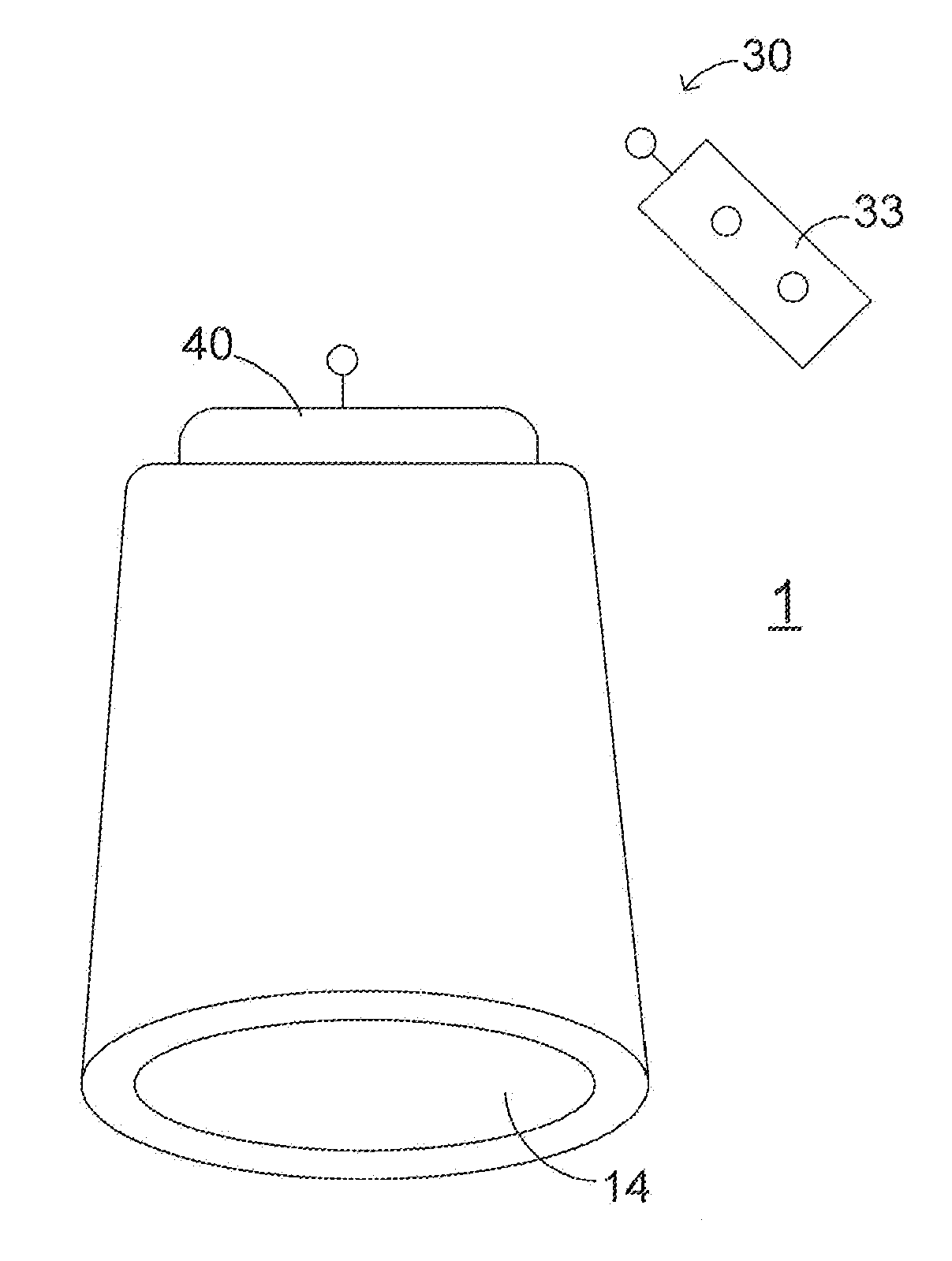
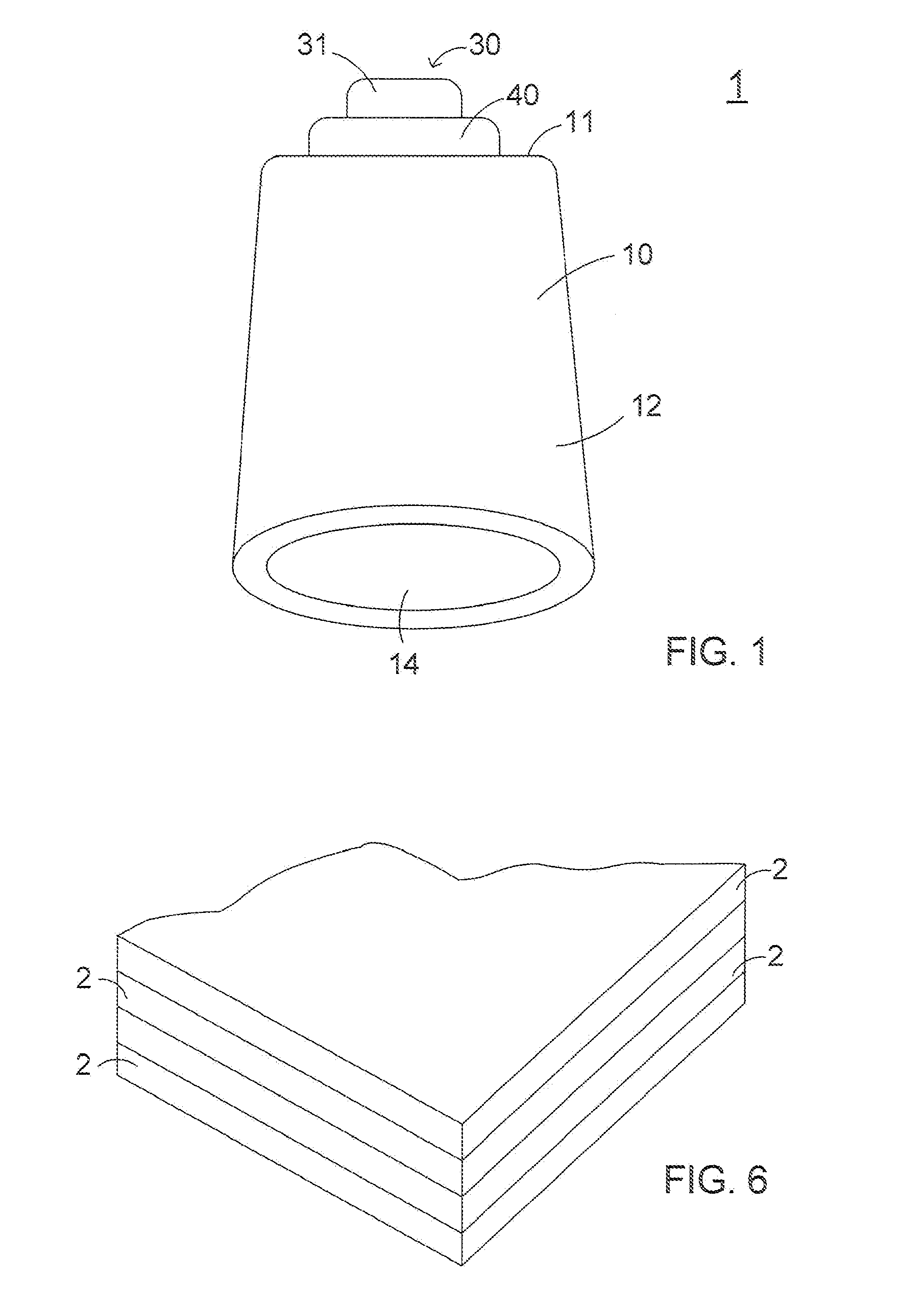
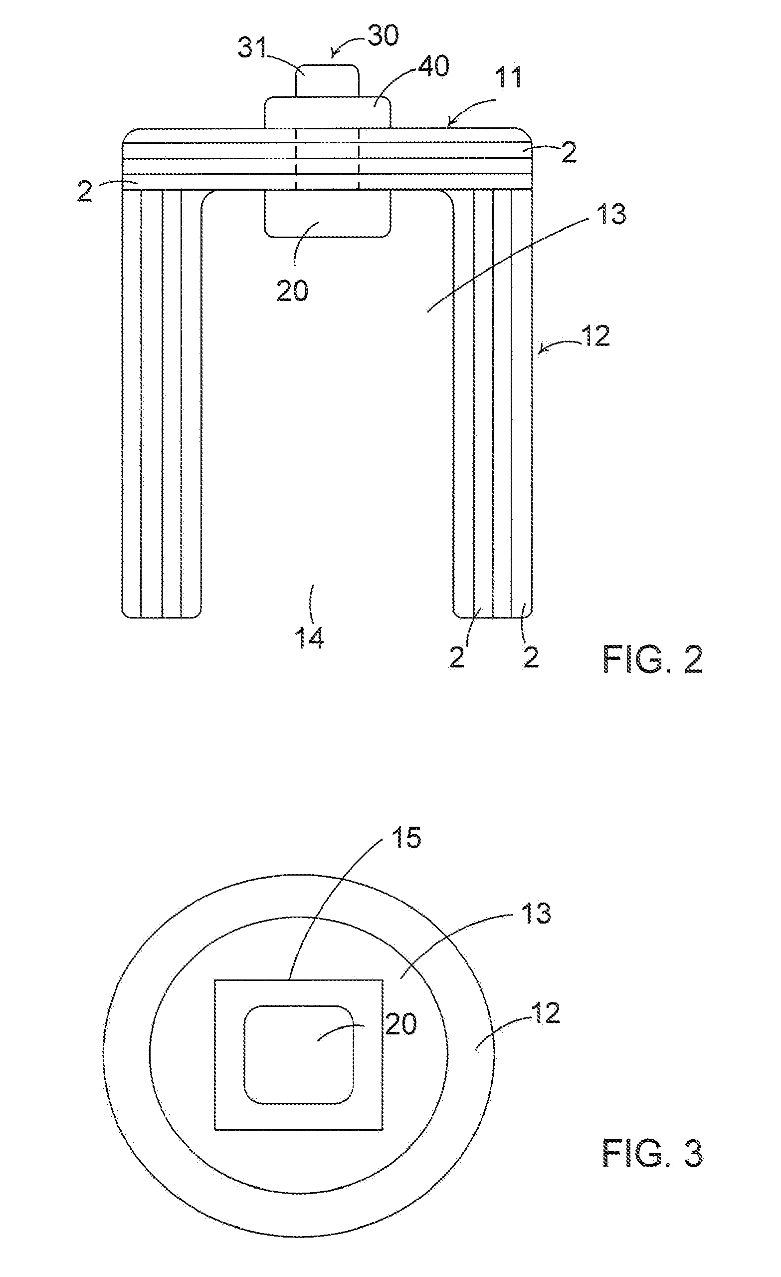
[0019]A sound focusing mechanism 1 in accordance with the present invention will now be described in greater detail in connection with FIGS. 1-5. The sound focusing mechanism 1 described herein will be used to determine the transmission loss of an object such as a wall, ceiling or other structure. The sound focusing mechanism 1 produces a sound that can be substantially localized onto or into an object. The sound focusing mechanism 1 will be used to locate and identify acoustic leakage points in a structure, including but not limited to walls, ceilings, floors, pipes, windows, etc. In either case, the mechanism 1 provides the individual with a simple means for locating areas of poor transmission loss or areas of high acoustic leakage so that possible remedies be readily identified and localized. From the determination of the leakage points or transmission loss, it is possible for the person or persons performing acoustic modifications on the structure to identify certain remedies fo...


PUM

PropertyMeasurementUnit
frequencyaaaaaaaaaa
frequencyaaaaaaaaaa
duration of timeaaaaaaaaaa

Abstract

A sound focusing mechanism for generating a focused source of sound, which can be used to identify the transmission loss of an object or identify areas of acoustic leakage is disclosed. The sound focusing mechanism includes a housing having at least one wall formed from a material having high sound insulating properties. A sound generating device for generating a sound is located within a central cavity within the housing. An actuator assembly is operatively connected to the sound generating device for selectively operating the sound generating device. The wall is configured to limit the transmission of the sound there through such that a focused beam or pulse sound is emitted from the mechanism through the opening.

Description

CROSS REFERENCE TO RELATED APPLICATION[0001]This application relates to and claims priority to U.S. Provisional Application No. 60 / 479,189, entitled “Sound Focusing Mechanism and Method of Determining Acoustic Leakage of an Object and Method of Determining the Transmission Loss of an Object,” filed on Jun. 18, 2003, the disclosure of which is specifically incorporated herein by reference.BACKGROUND OF THE INVENTION[0002]1. Field of the Invention[0003]The present invention relates to a sound focusing mechanism that generates a high sound pressure level, denoted throughout this document as decibel, and highly focused signal that is used in connection with sound proofing to locate areas of acoustic leakage. The sound focusing mechanism is also used in connection with the determination of the transmission loss of an object. The present invention is also directed to a method of locating acoustic leakage points in an object in order to improve sound proofing by focusing a high decibel sou...

Claims


Application Information

Patent Timeline
Patent Type & Authority Patents(United States)
IPC IPC(8): G01N24/00G10K11/00H03G3/00H04R29/00H04R17/00G01H15/00G10K11/26
CPCG01H15/00G10K11/26H04R29/001
Inventor SCHNITTA, BONNIE S.ISRAEL, MASON A.
Owner NOISEOUT
Learn More