Plasma etching apparatus

a technology of etching apparatus and plasma, which is applied in the direction of coating, chemical vapor deposition coating, electric discharge tube, etc., can solve the problems of substrate distorted, substrate distorted, and inability to easily achieve substrate alignment, etc., to achieve controllable etching process profile, improve etching rate, and high density

Inactive Publication Date: 2011-02-01
JUSUNG ENG
View PDF17 Cites 8 Cited by
  • Summary
  • Abstract
  • Description
  • Claims
  • Application Information

AI Technical Summary

Benefits of technology

[0015]The present invention is conceived to solve the aforementioned problems in the prior art. An object of the present invention is to provide a plasma etching apparatus, wherein inductively coupled plasma is employed to generate plasma with high density, thereby improving an etching rate and controlling the profile of an etching process at a low processing pressure.

Problems solved by technology

However, since a thin film is formed over the entire surface of the substrate upon deposition of the thin film and an etching process targets on a portion of the thin film at the center of the substrate, portions of the thin film in an edge area of the substrate remain un-removed.
In a case where subsequent processes are carried out without removing the thin film or accumulated particles in the edge area of the substrate, many problems may occur, for example, the substrate may be distorted, or the alignment of the substrate may not be easily achieved.
In case of the wet-etching process, it is difficult to locally remove the thin film and the particles only in the edge area of the substrate due to difficulty in controlling the process.
In addition, the use of various chemicals leads to an increase in production costs and causes environmental problems such as wastewater treatment.
However, since a conventional plasma etching apparatus for etching an edge area of a substrate is a capacitive coupled plasma (CCP) type., wherein plasma is generated through discharging between two opposite electrodes, the apparatus has a disadvantage in that an etching rate is deteriorated due to lower density of plasma.
In addition, since the electrodes are attached to the stage and the outer periphery of the insulator and plasma is generated under a high pressure, there is a problem in that in a case where the conventional apparatus is used to etch an edge area of the wafer, the plasma is spread to a central area of the wafer, so that a pattern at the central area thereof may be affected or damaged.
In addition, gases produced during the etching process cannot be smoothly exhausted from spaces defined by the cathode ring, the anode ring and the view ring.
Thus, there is a problem in that particles generated during etching cannot be effectively removed and thus may be accumulated at a lower portion of the substrate.

Method used


Image

  • Plasma etching apparatus
  • Plasma etching apparatus
  • Plasma etching apparatus

Examples


Embodiment Construction

[0028]Hereinafter, a preferred embodiment of the present invention will be described in detail with reference to the accompanying drawings. However, the present invention is not limited to the embodiment but may be implemented into different forms. These embodiments are provided only for illustrative purposes and for full understanding of the scope of the present invention by those skilled in the art. Throughout the drawings, like elements are designated by like reference numerals.

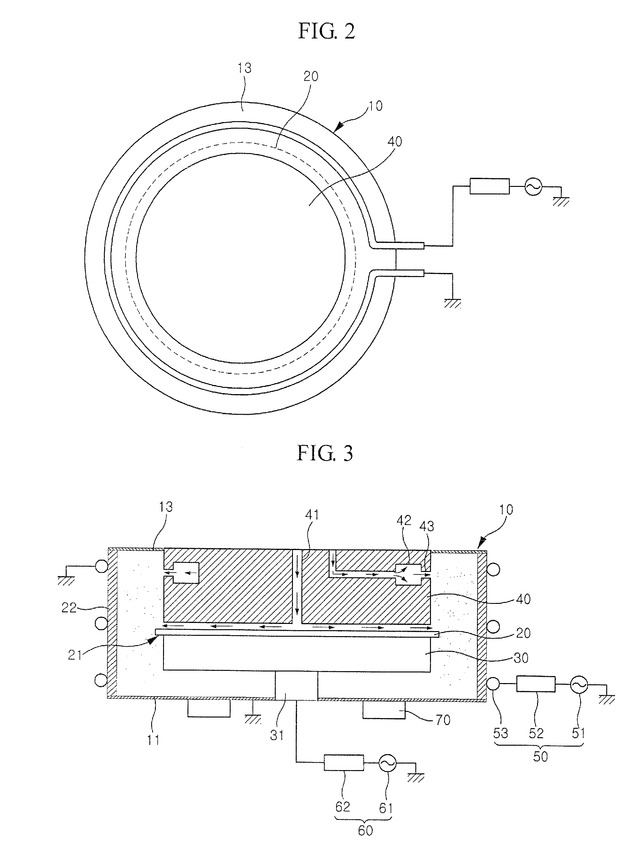
[0029]FIG. 1 is a sectional view conceptually showing a plasma etching apparatus according to an embodiment of the present invention. FIG. 2 is a plan view of the plasma etching apparatus according to the embodiment.

[0030]Referring to FIGS. 1 and 2, the plasma etching apparatus of this embodiment comprises a chamber 10, a substrate support 30 on which a substrate 20 is seated, a shield 40 for preventing plasma from being generated in a region of a top surface of the substrate 20 except an edge portion 21 t...


PUM

PropertyMeasurementUnit
widthaaaaaaaaaa
internal pressureaaaaaaaaaa
diameteraaaaaaaaaa

Abstract

The present invention relates to a plasma etching apparatus, which comprises a chamber, a substrate support disposed inside the chamber to support a substrate, a shield disposed with a gap on the substrate such that plasma is not generated therein while allowing an edge portion of the substrate to be exposed, an antenna disposed at a position on an outer wall of the chamber to apply plasma-generating power to an area between the edge portion of the substrate and an inner wall of the chamber, and a bias-applying unit for applying bias to the substrate support. According to the present invention, the shield and the substrate support prevent plasma from being generated at other portions of a substrate except an edge portion of the substrate. Inductively coupled plasma is employed to generate plasma with high density, thereby removing a thin film and particles remained at the edge portion of the substrate. In addition, by means of the discharging of inductively coupled plasma, it is possible to improve an etching rate at the edge portion of the substrate and to adjust the profile of an etching process at a low processing pressure.

Description

CROSS-REFERENCE TO RELATED APPLICATIONS[0001]This U.S. non-provisional patent application claims priority under 35 U.S.C. §119 of Korean Patent Applications 2005-0069391 filed on Jul. 29, 2005, the entire contents of which are hereby incorporated by reference.BACKGROUND OF THE INVENTION[0002]1. Field of the Invention[0003]The present invention relates to a plasma etching apparatus, and more particularly, to a plasma etching apparatus, wherein inductively coupled plasma is used to remove film materials on an edge area of a substrate.[0004]2. Description of the Related Art[0005]Semiconductor devices and liquid crystal display devices are fabricated on substrates through multiple thin film deposition and etching processes. That is, a thin film is deposited on a substrate, and a portion of the thin film at the center of the substrate is removed through an etching process using an etching mask, thereby forming a device with a desired thin film pattern. However, since a thin film is forme...

Claims


Application Information

Patent Timeline
Patent Type & Authority Patents(United States)
IPC IPC(8): C23C16/00H01L21/306
CPCH01J37/321H01J37/3244H01J37/32449H01J37/32623H01J37/32706H01L21/3065
Inventor JEON, BU-IL
Owner JUSUNG ENG
Why Eureka
Try Eureka