
Container and device for production of such container

a technology for containers and containers, applied in the field of containers, can solve the problems of receptacle elements overflowing into the hollow chamber, unable to return, and unable to be removed from the container for a removal process,

Active Publication Date: 2011-01-11
HANSEN BERND
View PDF42 Cites 15 Cited by
  • Summary
  • Abstract
  • Description
  • Claims
  • Application Information

AI Technical Summary

Benefits of technology

[0008]An object of the present invention is to provide an improved container such that the medium to be dispensed no longer remains in the hollow chamber of the head or sealing element and cannot be returned by the essentially funnel-shaped geometries of the dispensing opening to the receptacle element as the actual container interior. Within the larger framework, free container shaping tailored to customer specifications and to aspects of practicability is possible.
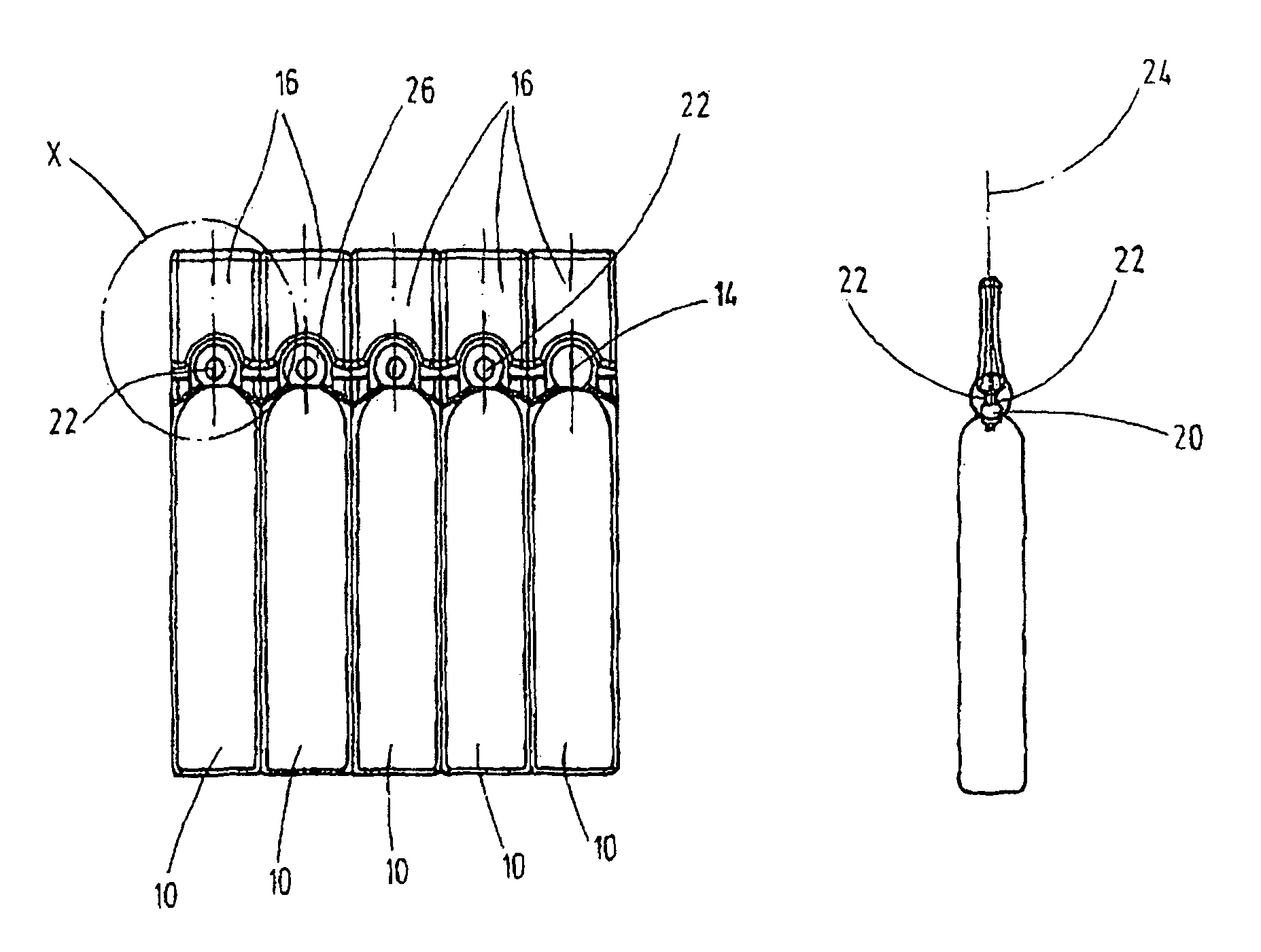
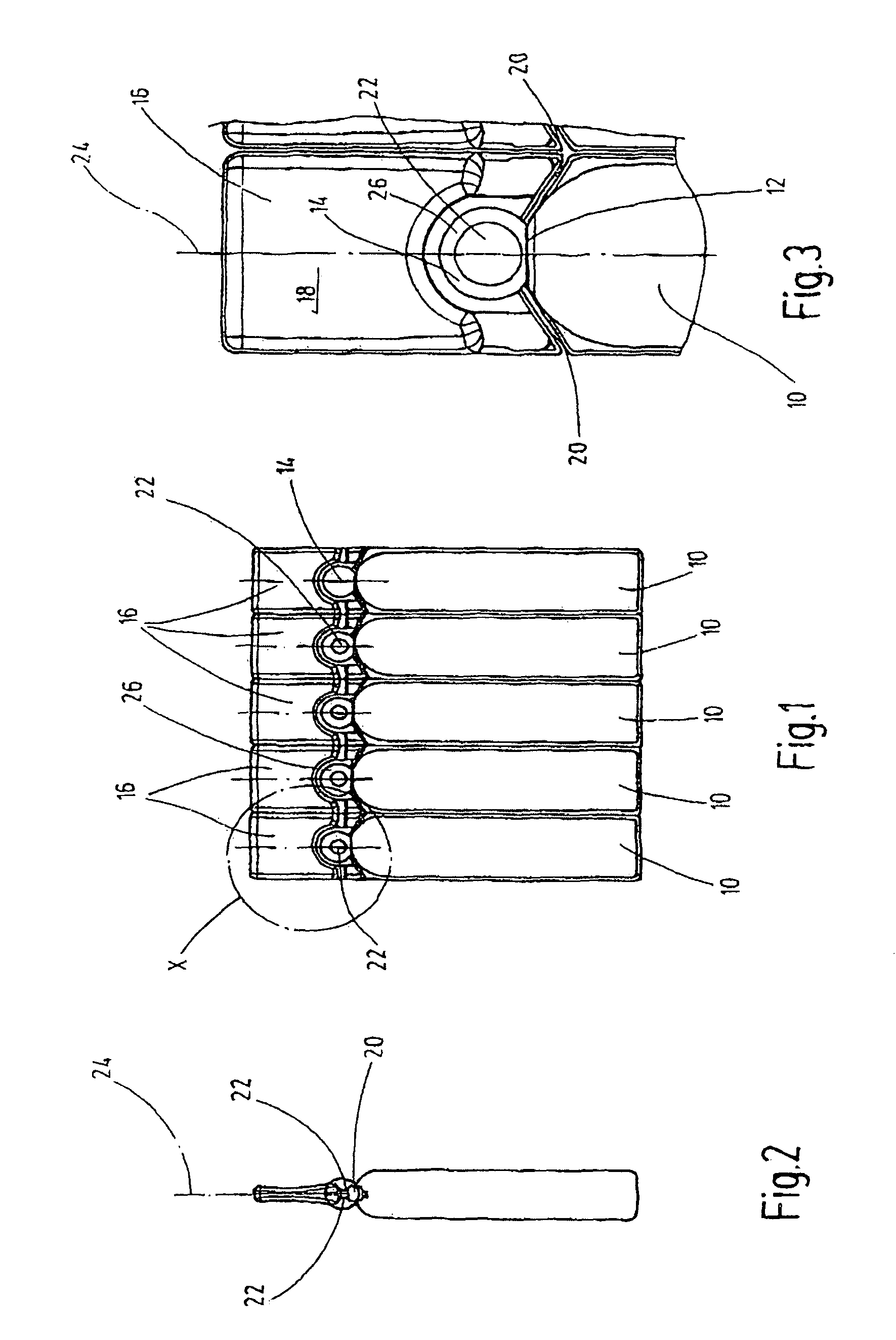
[0009]This object is basically achieved by a container where, to reduce the free volume of the hollow chamber, the opposite wall components of the sealing element are displaced into the hollow chamber to prevent the dispensing medium stored in the receptacle element from being able to penetrate into the hollow chamber. In contrast to the known solution, no elevated wedge-shaped or dome-shaped region is on the free top end of the hollow closure section of the head component as a hollow chamber. Rather, the facing wall sections that border the hollow chamber are moved toward each other. In this way, the arrangement reduces the free chamber volume, since the facing wall sections are displaced into the hollow chamber, leading to markedly improved volume reductions.
[0010]The opposite adjacent wall components displaced toward the dispensing opening into the hollow chamber transversely or obliquely thereto reduce the hollow chamber volume. The medium to be dispensed, even in the form of a very thin liquid medium, then cannot travel at all into the hollow chamber, but remains in the hollow receptacle element. In this respect, in the present invention, the problem does not arise of having to return to the container interior the medium to be dispensed which penetrates into the hollow chamber by the oblique surfaces of the delivery mouth piece extending in a straight line. Rather, for this purpose, the shape of the dispensing opening and delivery mouthpiece can be freely selected within a widely drawn framework, making possible short longitudinal dimensions in implementation, especially in the axial direction of the container.
[0011]The hollow chamber, in particular in the form of a ball, is also used during shaping the plastic material over an “edge”. Such shaping can reduce the wall thickness of the plastic material for forming desired point of separation.
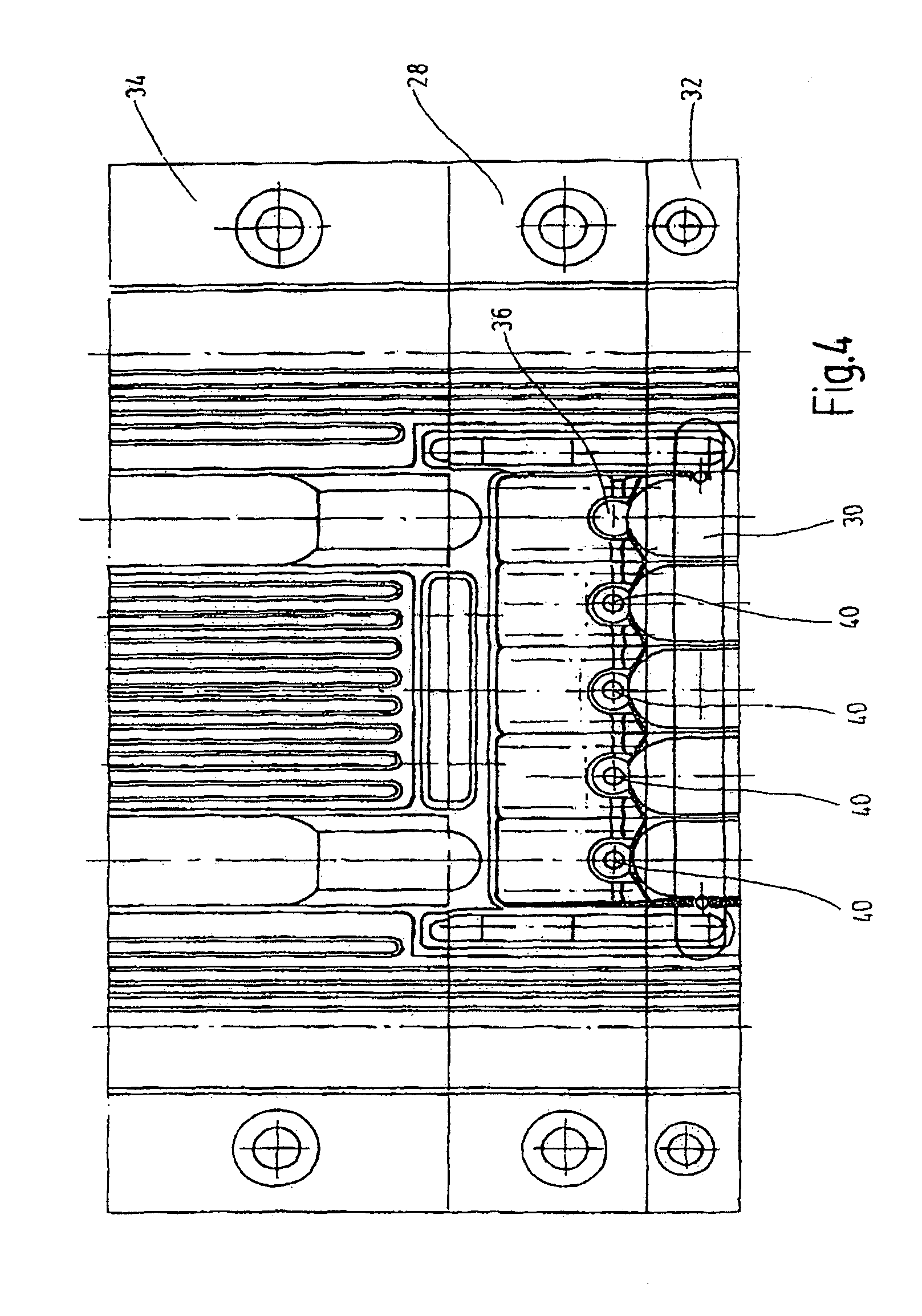
[0013]On the basis of these known devices, the device of the present invention is characterized in that mold parts can be triggered within the mold recesses which relate to the hollow chambers. These parts facing each other in the retracted position enable complete formation of the hollow chamber. In the extended position, they move the adjacent wall components of the hollow chamber toward each other as the free chamber volume is reduced in molding. These mold parts, by preference are designed as pneumatically driven plungers, can be housed in a space-saving design within the respective mold jaws with their mold recesses, and can be triggered in a timely and controlled manner. By integrating the additional mold parts within the mold jaws space-saving accommodation is ensured, as is a reliable configuration which can be implemented cost-efficiently.

Problems solved by technology

For example, bordering wall components of the container are not pushed against each other such that closure of the dispensing opening might unintentionally occur.
The latter however then results in the disadvantage that the medium stored in the receptacle element overflows into the hollow chamber and then can no longer flow back, especially when the fluid medium stored in the hollow chamber is held in the hollow chamber due to its surface tension.
If part of the medium to be dispensed remains in the hollow chamber, it is lost for a removal process from the container.
This loss is especially disadvantageous when exact dosing is critical during dispensing or the medium to be dispensed is inherently very expensive or when exact mixing ratios and concentrations for later use are critical when suspensions are being dispensed.
These proposed measures alone can still result in loss of the active agent in the hollow chamber of the sealing element designed as the head component.
In spite of these measures, especially for fluid media with a high surface tension, it is possible that they will settle in the remaining hollow chamber volume and will then not be available for removal.
The container walls necessarily provided and extending in a straight line in the area of the delivery mouth piece limit the free shape of container geometries.

Method used


Image

  • Container and device for production of such container
  • Container and device for production of such container
  • Container and device for production of such container

Examples


Embodiment Construction

[0022]The container according to an exemplary embodiment of the present invention is made in particular in the form of a hermetically sealed ampule. A combination of five of these containers is shown in FIG. 1, the individual containers being separable from each other along their adjoining longitudinal side edges to form an individual container. Almost any number of rows of or numbers of containers to be manufactured, as well as individual containers, can be produced.

[0023]The containers are produced from a moldable plastic material, for example, a polyamide or a polyethylene material. Furthermore, these container products can be produced in a co-extrusion process with a multilayer wall structure or with a coating on the plastic to increase its impermeability, for example, by vacuum-coating the container on the outside. By preference, materials are used that can be easily used for a blow-fill-seal process, and are known in the trade under the brand name “Bottelpack®”, for example.

[0...


PUM


Abstract

A container has a hollow receptacle element (10) for holding a medium to be dispensed, and a dispensing opening (12) communicating with a hollow chamber (14) of a sealing element (18). The sealing element (18) is detachable by a point of separation (20). To reduce the free volume of the hollow chamber (14), opposite wall components (22) of the sealing element (18) are displaced into the hollow chamber (14). The dispensing medium stored in the receptacle element (10) is prevented from being able to unintentionally penetrate into the hollow chamber (14) where it would no longer being available for a removal process. The invention also relates to a device for production of such a container.

Description

FIELD OF THE INVENTION[0001]The present invention relates to a container, a hermetically sealed ampule in particular, having a hollow receptacle element for holding a medium to be dispensed. The container has a dispensing opening communicating outside the receptacle element, with a hollow chamber of a sealing element forming the head component of the container. The hollow chamber keeps the dispensing opening clear. The sealing element is detachably connected to the receptacle element by a point of separation in the area of the dispensing opening. The present invention furthermore relates to a device for producing the container according to this configuration.BACKGROUND OF THE INVENTION[0002]Containers of the indicated type are used in particular to store media of the most varied type to be dispensed in the hollow receptacle element. For example, the media is in the form of medical solutions, suspensions and / or semisolid preparations such as gels. To quickly clear the dispensing open...

Claims


Application Information

Patent Timeline
IPC IPC(8): B65D47/10
CPCA61J1/067B65D1/095
Inventor HANSEN, BERND
Owner HANSEN BERND
Learn More