
Substrate for light-emitting diode, and light-emitting diode

a technology of light-emitting diodes and substrates, which is applied in the direction of solid-state devices, natural mineral layered products, water-setting substance layered products, etc., can solve the problems of white light-emitting diodes using substrates, uneven color of light-emitting diodes, and uneven distribution of fluorescent powders

Active Publication Date: 2011-01-04
UBE IND LTD
View PDF26 Cites 5 Cited by
  • Summary
  • Abstract
  • Description
  • Claims
  • Application Information

AI Technical Summary

Benefits of technology

[0010]As a result of intensive studies, the present inventors have found that the above-described problems can be solved by bonding and stacking a specific material layer, and accomplished the present invention.
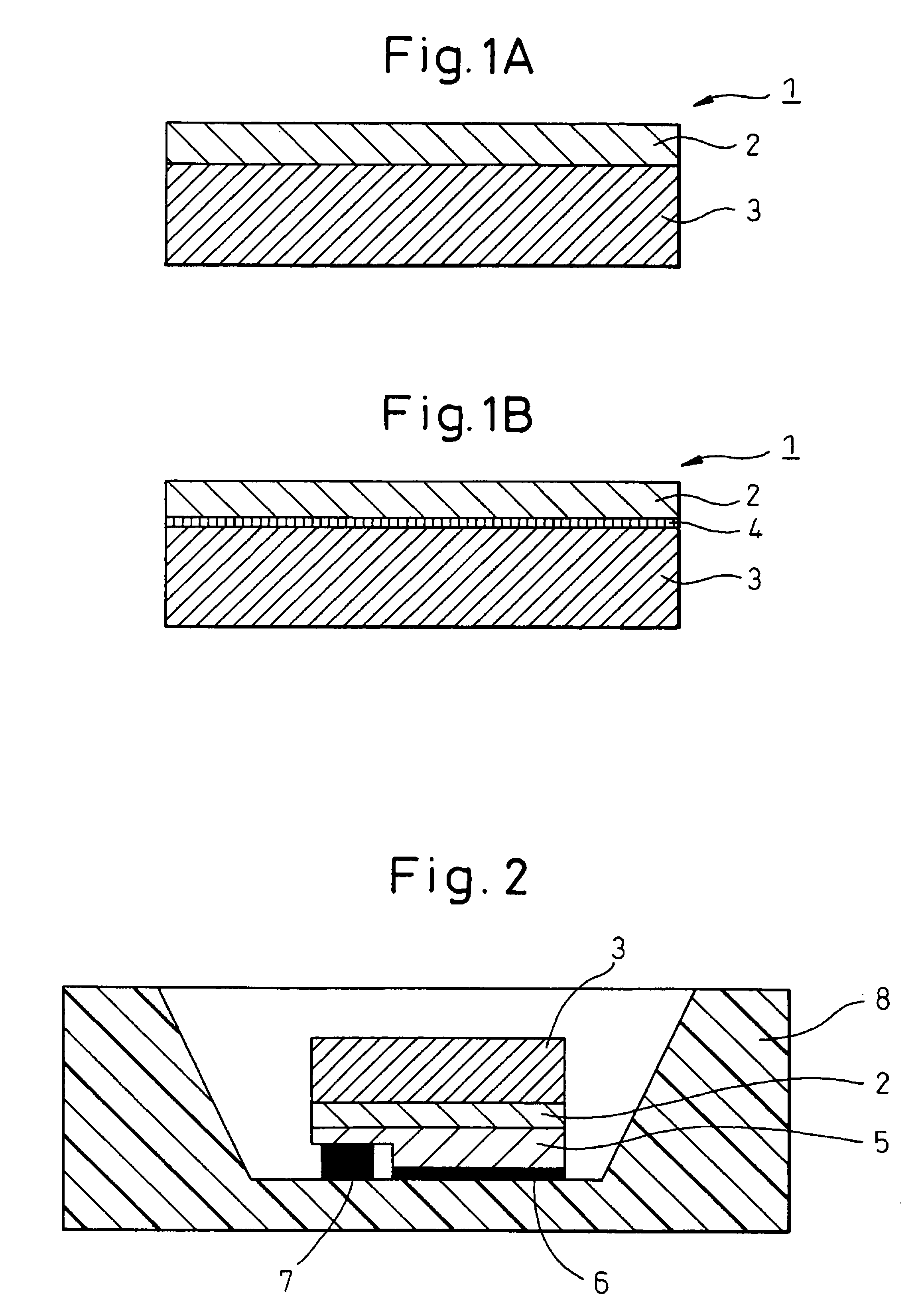
[0015]When the substrate for light-emitting diodes of the present invention is used, the substrate can work as a light emission surface without using fluorescent powder, a light-emitting diode element (semiconductor layer) can be easily formed thereon, and a light-emitting diode reduced in deterioration and assured of good light mixing and less color unevenness can be obtained.
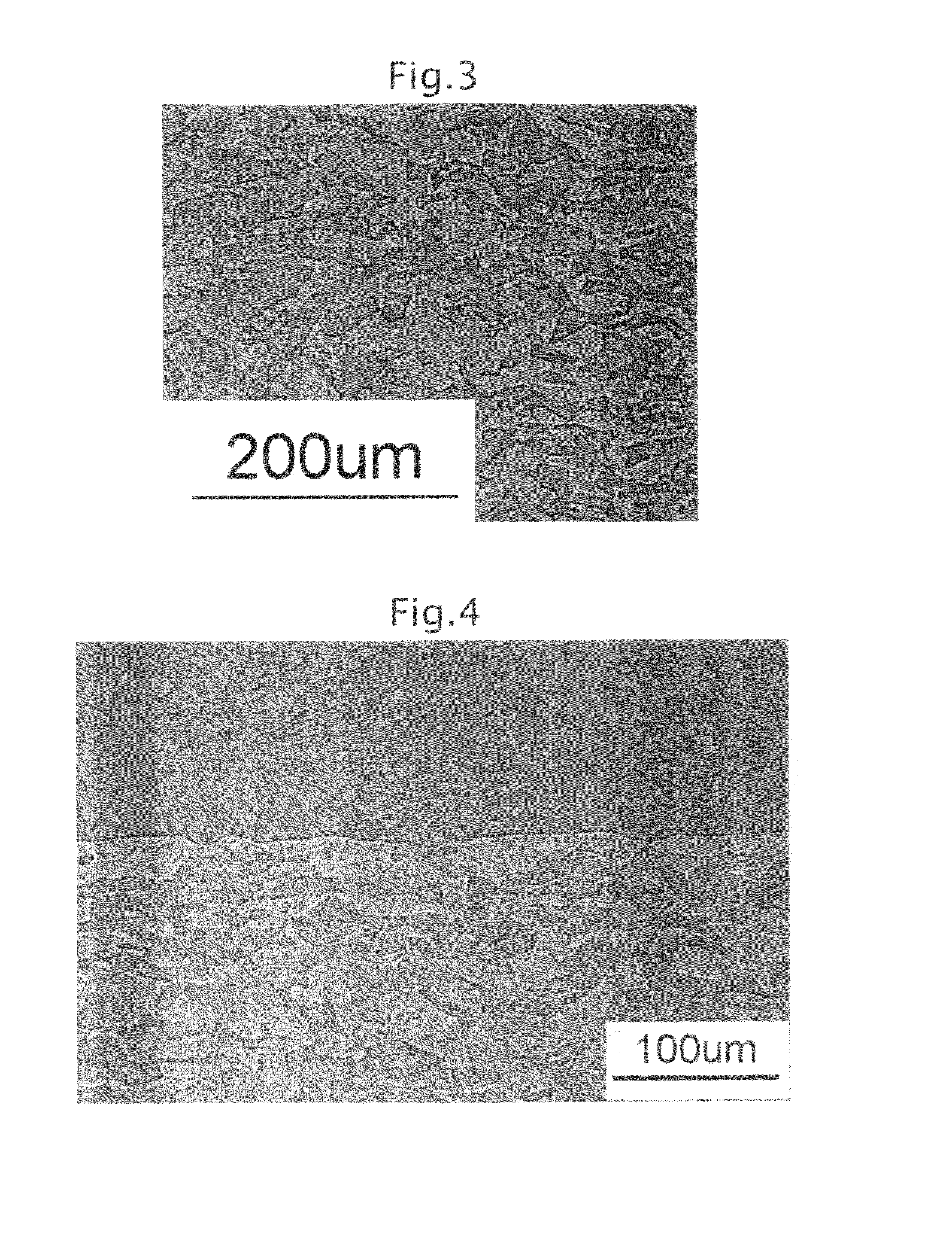
[0016]Also, by using the substrate of the present invention, in the production of an InGaN-based blue light-emitting element, an InGaN-based blue light-emitting element can be produced using a single crystal substrate such as Al2O3 having most effective performance, so that there can be obtained a white light-emitting diode where light emitted from the InGaN-based blue light-emitting element is introduced directly to the substrate, similarly to the ZnSe substrate, a part of the blue light is absorbed to emit yellow light while simultaneously transmitting the blue light, and at the same time, excitation light and fluorescence are effectively mixed by three-dimensional intertwining of a plurality of crystal phases to create uniform light. Moreover, a white light-emitting diode can be obtained only by producing a blue-light emitting element on this substrate, and the production process of a light-emitting diode can be greatly simplified. Furthermore, a substrate enabling to control the color tone can be provided by allowing another fluorescent substance to be present on the bonding surface at the time of bonding the single crystal substrate and the ceramic composite, and the substrate is also characterized in that the color tone of a light-emitting diode can be very easily controlled. The ceramic composite is given broad latitude in the light emission wavelength by this control of color tone, as a result, the compositional design of the ceramic composite material is broadened in the latitude.

Problems solved by technology

However, in this method, for example, uneven distribution of the fluorescent powder contained or a fluctuation in the amount of fluorescent powder among individual light-emitting diodes readily occurs when applying the coating layer, and it has been pointed out that the light-emitting diode has color unevenness attributable thereto.
However, the actual performance of the white light-emitting diode using a substrate with a YAG (111) face described in Japanese Unexamined Patent Publication (Kokai) No. 2003-204080 above is not known.

Method used


Image

  • Substrate for light-emitting diode, and light-emitting diode
  • Substrate for light-emitting diode, and light-emitting diode
  • Substrate for light-emitting diode, and light-emitting diode

Examples


example 1

[0046]An α-Al2O3 powder (purity: 99.99%) and a Y2O3 powder (purity: 99.999%) were weighed to give a molar ratio of 82:18 and a CeO2 powder (purity: 99.99%) was weighed to amount of 0.03 mol per mol of Y3Al5O12 produced by the reaction of oxides charged. These powders were wet-mixed in ethanol by a ball mill for 16 hours, and then the solvent ethanol was removed by using an evaporator to obtain a raw material powder. This raw material powder was preliminarily melted in a vacuum furnace and used as a raw material for unidirectional solidification.

[0047]The obtained raw material was directly charged into a molybdenum crucible and after setting the crucible in a unidirectional solidification apparatus, the raw material was melted under a pressure of 1.33×10⁻³ Pa (10−5 Torr). In the same atmosphere, the crucible was moved down at a speed of 5 mm / hour, whereby a solidified body comprising a garnet crystal Y3Al5O12:Ce and an α-type aluminum oxide crystal Al2O3 was obtained. This solidified...

example 2

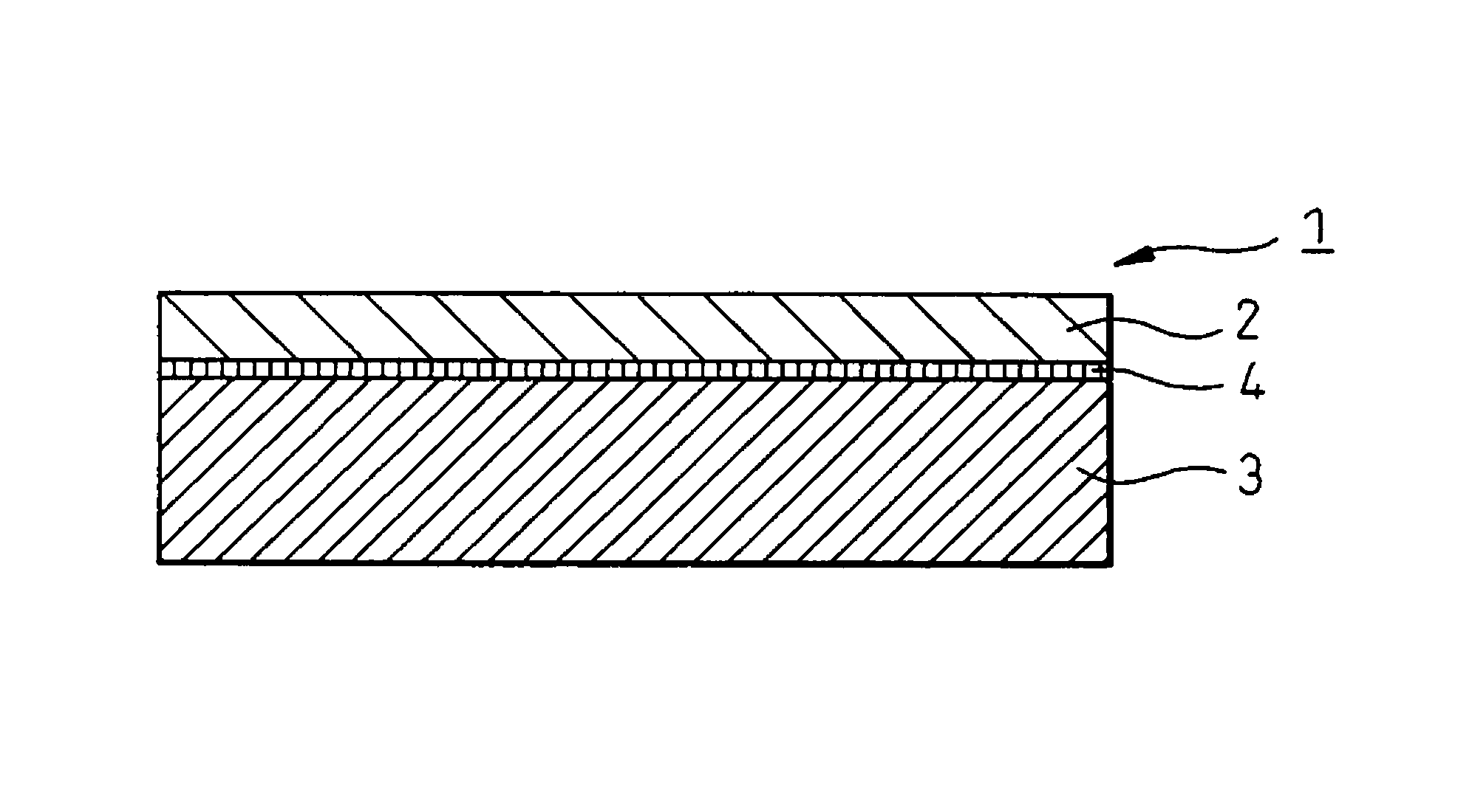
[0053]A solution containing 30% of spherical amorphous silica having a diameter of 10 to 20 nm was coated by a spin coater on the plate of 10 mm×10 mm of ceramic composite for light conversion produced in Example 1. After the coating, this substrate was heated at 60° C. to remove the solvent component. Thereafter, the same Al2O3 single crystal plate as that of Example 1 was placed on the amorphous silica-coated surface of this plate of ceramic composite for light conversion, and the obtained sample was set in a hot-press device, heated at 1,300° C. while applying a pressure of 0.03 MPa, kept for 2 hours and then gradually cooled. FIG. 6 shows the substrate obtained. The upper side is the Al2O3 single crystal plate and the lower side is the plate of ceramic composite for light conversion. A silica phase which is an adhesion phase is present at the interface.

[0054]When a light-emitting diode was produced in the same manner as in Example 1 by using the above-produced substrate for ligh...

example 3

[0055]An epoxy resin and a CaAlSiN3 powder as a red fluorescent substance were weighed at a weight ratio of 1:1 and mixed in a paint shaker for 30 minutes to obtain a mixed slurry. This slurry was placed in a vacuum desiccator to remove bubbles, and the resulting paste was coated on the plate of ceramic composite for light conversion produced in Example 1. Furthermore, a sapphire substrate having formed thereon a blue light-emitting element produced by the same method as in Example 1 was laminated with the ceramic composite for light conversion. This material was placed in a constant-temperature bath at 150° C. and the resin was cured. The obtained substrate was divided by drawing a scribe line and applying external force, whereby a light-emitting diode device was obtained.

[0056]FIG. 7 shows the light emission spectrum of the device obtained. Emission of blue light, emission of yellow fluorescence from the substrate and emission of red light from the red fluorescent substance were a...


PUM

PropertyMeasurementUnit
temperatureaaaaaaaaaa
timeaaaaaaaaaa
temperatureaaaaaaaaaa

Abstract

A substrate for light-emitting diodes, obtained by stacking a single crystal layer to form a light-emitting diode element onto a ceramic composite layer for light conversion, the ceramic composite layer having been formed by a unidirectional solidification method so that the ceramic composite layer comprises a solidified body having formed therein at least two or more oxide phases selected from single metal oxides and complex metal oxides to be continuously and three-dimensionally entangled with each other, with each oxide phase having a single crystal orientation, wherein at least one oxide phase out of the oxide phases in the solidified body contains a metal element oxide capable of emitting fluorescence.

Description

RELATED APPLICATION[0001]This is a §371 of International Application No. PCT / JP2006 / 315695, with an international filing date of Aug. 2, 2006 (WO 2007 / 018222 A1, published Feb. 15, 2007), which is based on Japanese Patent Application No. 2005-231505, filed Aug. 10, 2005.TECHNICAL FIELD[0002]The present invention relates to a substrate for light-emitting diodes usable in a display, a light, a backlight source and the like, and a light-emitting diode using the substrate for light-emitting diodes.BACKGROUND ART[0003]In recent years, studies have been aggressively made to develop a white light-emitting diode in which a blue light-emitting element using a nitride-based compound semiconductor is employed as a light emission source. A white light-light emitting diode is lightweight, uses no mercury and has long life, and therefore, demands are expected to rapidly expand in the future. A most commonly employed method for converting blue light of a blue light-emitting element into white ligh...

Claims


Application Information

Patent Timeline
Patent Type & Authority Patents(United States)
IPC IPC(8): H01L33/00H01L21/00H01L33/50
CPCC04B35/01C04B35/117C04B35/44C04B35/58C04B35/653C09K11/7774H01L33/501H05B33/14C04B2235/3217C04B2235/3222C04B2235/3225C04B2235/3229C04B2235/3286C04B2235/764C04B2235/80C04B2235/963C04B2235/9661H01L2224/10
Inventor SAKATA, SHIN-ICHIMITANI, ATSUYUKI
Owner UBE IND LTD
Learn More