
Circuit and system for programming a floating gate

a floating gate and circuit technology, applied in the field of low-current analog integrated circuitry, can solve the problems of affecting the accuracy of the gate, consuming a large amount of power, and additional circuitry for providing other voltage levels, so as to improve the accuracy, improve stability, and facilitate the effect of rapid programming

Active Publication Date: 2010-12-28
TRIUNE IP
View PDF2 Cites 20 Cited by
  • Summary
  • Abstract
  • Description
  • Claims
  • Application Information

AI Technical Summary

Benefits of technology

"The present invention provides advances in the art with novel apparatus directed to providing low-current floating gate architectures with offset mitigation capabilities and improved accuracy. The invention uses an iterative floating gate device and floating reference node programming technique for improved accuracy and stability. The invention also includes a programable floating gate circuit, a suitably equipped circuit in a tunneling mode, and circuitry for monitoring the output of the circuit and selectably reiterating the tunneling using an incrementally changed reference voltage. The invention has advantages including improved accuracy, rapid programming, improved stability over a range of operating conditions, and efficient, ultra-low power requirements."

Problems solved by technology

Unfortunately, however, band gap references are limited to a fixed voltage level, typically about 1.2V.
The additional circuitry required for providing other voltage levels, such as fixed gain amplifiers for example, can be seriously detrimental to accuracy.
Additionally, band gap voltage reference circuits generally draw a significant amount of power, presenting an additional problem in applications in which low power consumption is desirable.
Floating gate voltage reference circuits are often chosen for their low power requirements, but can be problematic in applications requiring a high degree of accuracy in providing a selected programmed voltage level, particularly over time and changes in temperature.
The accuracy of common floating gate circuits is limited for at least two primary reasons.
Firstly, the potential on a floating gate decreases after it is programmed due to the capacitance inherent in the tunneling device.
This voltage offset is well-defined and predictable, but is unavoidable in prior art floating gate voltage reference circuits because the capacitance of the tunneling device cannot be completely eliminated.
Secondly, the accuracy of prior art floating gate voltage reference circuits is also hampered by the decay of the theoretically permanent charge on the floating gate over time.

Method used


Image

  • Circuit and system for programming a floating gate
  • Circuit and system for programming a floating gate
  • Circuit and system for programming a floating gate

Examples


Embodiment Construction

[0024]While the making and using of various exemplary embodiments of the invention are discussed herein, it should be appreciated that the present invention provides inventive concepts which can be embodied in a wide variety of specific contexts. It should be understood that the invention may be practiced with various electronic circuits, microelectronic circuit components, systems, system components, and subsystems without altering the principles of the invention. For purposes of clarity, detailed descriptions of functions, components, and systems familiar to those skilled in the applicable arts are not included. In general, the invention provides programmable analog voltage reference circuits for rapidly and accurately setting an output to a given selected voltage.

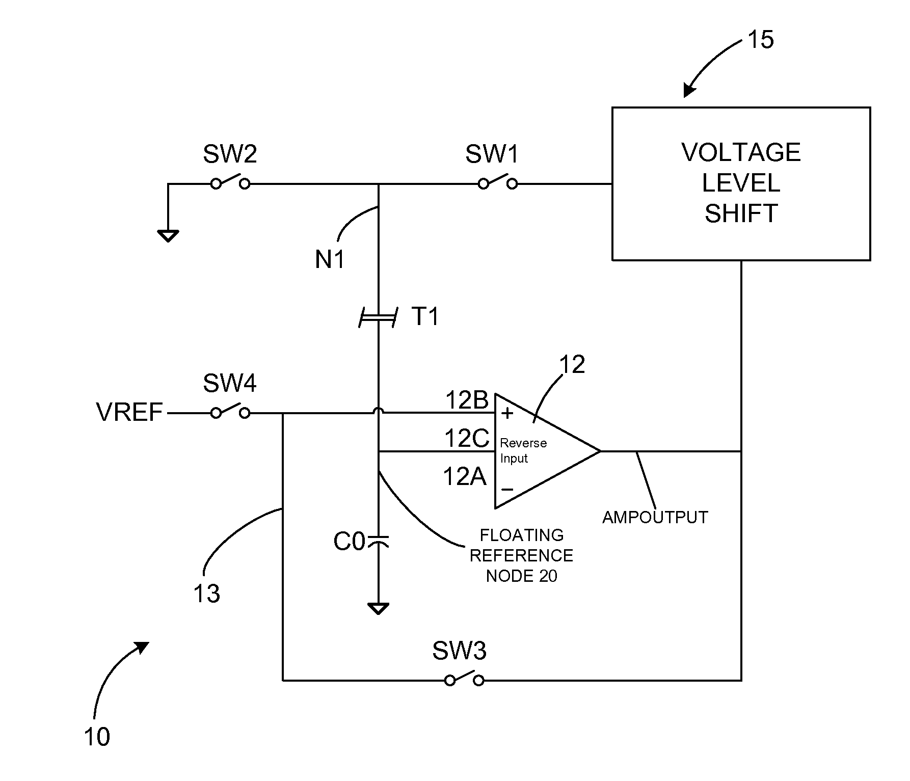
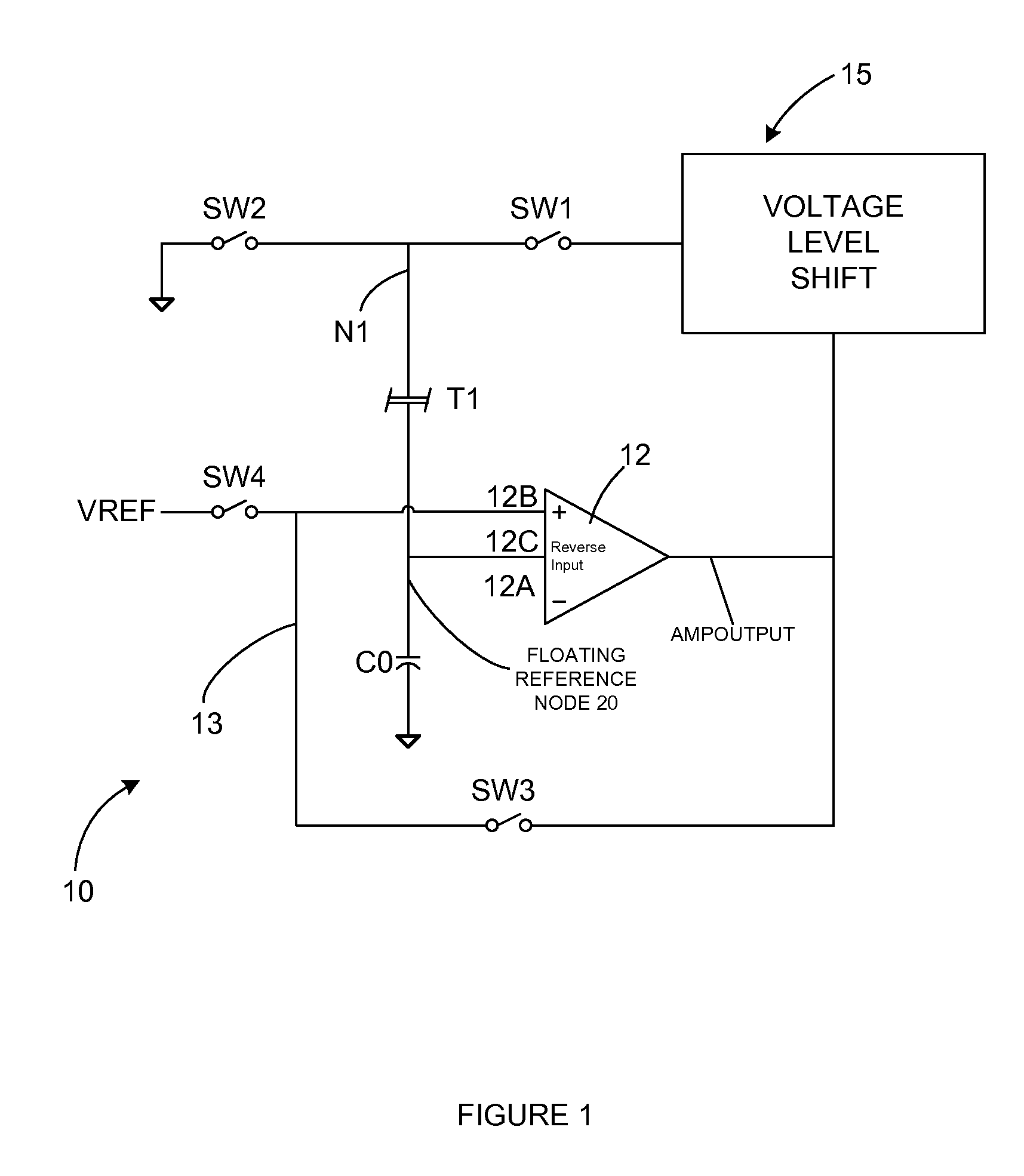
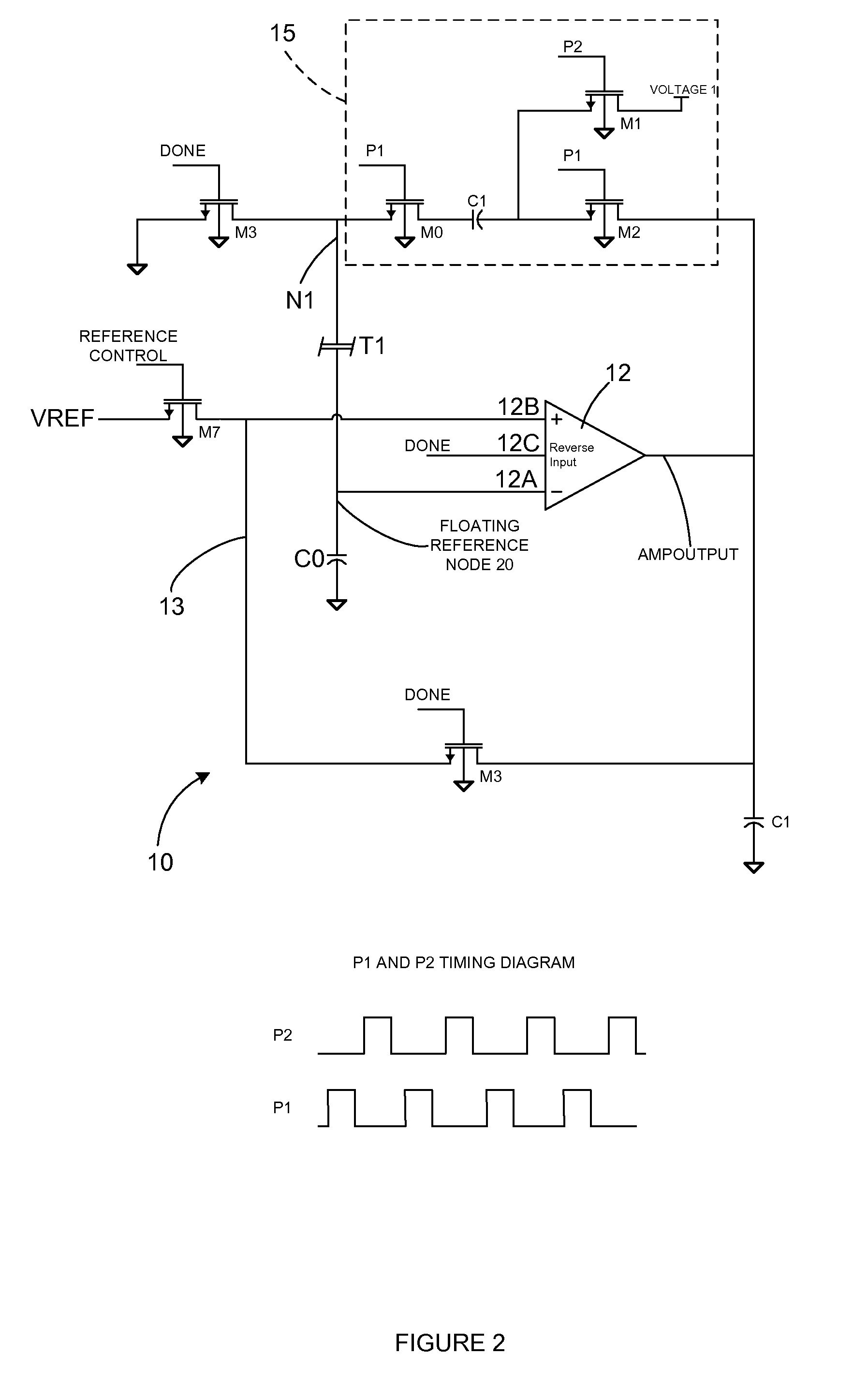
[0025]Now referring primarily to FIG. 1, the structure of an example of an embodiment of a programmable floating gate circuit 10 is shown in a simplified schematic, and its operation is described. An op amp 12 and a volt...


PUM


Abstract

The invention provides circuits and systems for programming a floating gate. A floating gate tunneling device is used with an analog comparing device in a circuit having a floating reference node and an offset-mitigating feedback loop for iteratively programming a floating gate, or multiple floating gates.

Description

PRIORITY ENTITLEMENT[0001]This application is entitled to priority based on Provisional Patent Application Ser. No. 61 / 082,403 filed on Jul. 21, 2008, which is incorporated herein for all purposes by this reference. This application and the Provisional Patent Application have at least one common inventor.TECHNICAL FIELD[0002]The invention relates to low-current analog integrated circuitry. More particularly, the invention relates to microelectronic floating gate circuit architectures and systems for their programming and operation.BACKGROUND OF THE INVENTION[0003]Programmable analog circuits are often required in applications where voltage accuracy and low power use are desirable traits.[0004]Band gap reference voltage circuits are frequently used in applications that require a high degree of voltage accuracy. Band gap voltage reference circuits are known for their capabilities for providing excellent accuracy and stability over time and a range of operating temperatures. Unfortunat...

Claims


Application Information

Patent Timeline
Patent Type & Authority Patents(United States)
IPC IPC(8): G11C11/34G11C16/04G11C7/00G11C5/14
CPCG11C27/005G11C16/0408G11C16/10G11C16/3468
Inventor TEGGATZ, ROSS E.CHEN, WAYNE T.SMITH, BRETTBLACKALL, ERIC
Owner TRIUNE IP
Learn More