
Lighting panels including embedded illumination devices and methods of making such panels

a technology of embedded illumination devices and lighting panels, which is applied in the direction of mass transit vehicle lighting, lighting support devices, instruments, etc., can solve the problems of high labor intensity, high labor intensity, and high labor intensity of laborers, and achieves the effects of reducing panel weight, volume, and easy retrofitting to existing aircra

Active Publication Date: 2010-12-28
THE BOEING CO
View PDF27 Cites 16 Cited by
  • Summary
  • Abstract
  • Description
  • Claims
  • Application Information

AI Technical Summary

Benefits of technology

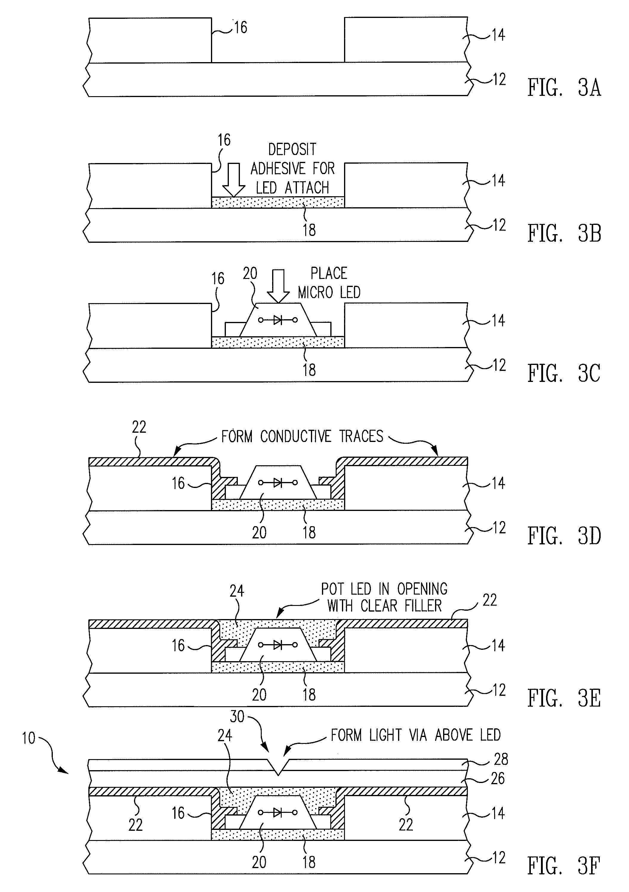
The patent describes a new method for making aircraft ceiling panels that creates a starry nighttime sky effect without using traditional methods. The panels are made by inserting a light source into a structural panel with openings, and then using electrically conductive traces and a decorative film to create a lighting effect. The panels are lighter, more easily installed, and can be retrofitted into existing aircraft. The technical effect of this method is to provide a more visually appealing and comfortable atmosphere for passengers during flight.

Problems solved by technology

The disadvantages and limitations of this prior art solution are that the method of producing the panels is costly, the resulting panels are relatively heavy, require intensive, ergonomically costly manual labor steps, take up a relatively large volume behind the ceiling panels and are difficult to retrofit into existing aircraft.

Method used


Image

  • Lighting panels including embedded illumination devices and methods of making such panels
  • Lighting panels including embedded illumination devices and methods of making such panels
  • Lighting panels including embedded illumination devices and methods of making such panels

Examples


embodiment 60

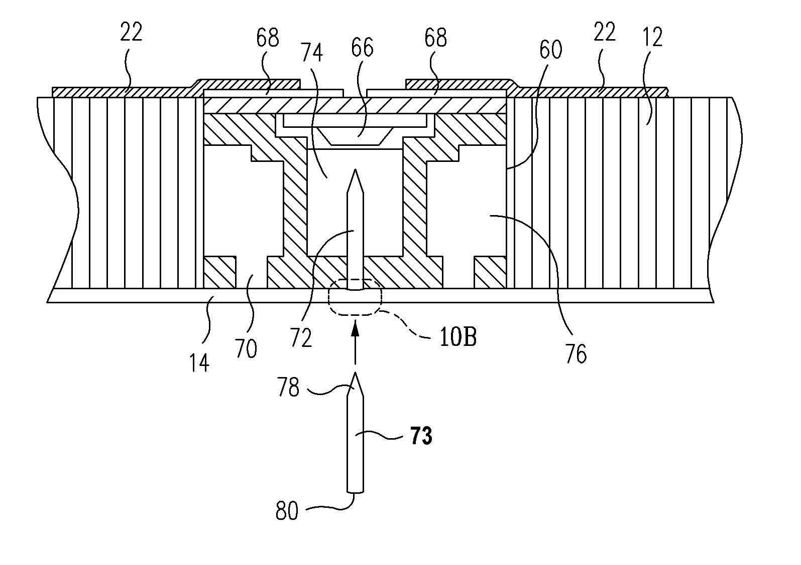
[0061]As may be seen by reference to FIGS. 13 and 14, the two-part panel insert 84 embodiment is similar to the single-part or integrated insert embodiment 60 above in many respects, except that it is divided into two mechanically separable parts, viz., an insert housing part 86 and an LED-mounting assembly and protective cover part 88. As described below, this arrangement enables an easy replacement of the associated LED 66 in case of a failure thereof. The housing part 86 comprises an opaque housing 62 having adhesive fill openings 70, and may include a trans-parent plug 74 defining a light path opening 72 into which the lens of the associated LED may be inserted, as above. The second part 88 of the insert comprises a PCB 64 mounting a downwardly facing micro LED 66, a pair of spring-loaded electrical contacts 90 respectively coupled to the anode and cathode of the LED 66 through the PCB and protruding downwardly therefrom, a protective cover 92, and engagement features 94 dispose...

embodiment 84

[0064]In the two-piece embodiment 84 of FIGS. 13 and 14, the housing part 86 is first installed in a through-opening of a structural panel (not illustrated), in a manner similar to that of the one-piece insert installation described above in connection with FIGS. 10A and 10B, and conductive traces (not illustrated) are then formed on the upper surface of the panel such that ends of the traces respectively overlap the conductive pads 96 of the housing part 86. The LED and cover assembly 88 is then mechanically coupled to the housing part 86 using the complementary fastener features 94, which causes the spring-loaded electrical contacts 90 of the LED and cover assembly 88 to make contact with and thereby establish electrical contact between the LEDs 66 and the respective traces.

[0065]FIG. 15 is a partial cross-sectional view of an aircraft ceiling panel 12 having a two-piece LED panel insert 84 similar to that of FIGS. 13 and 14 installed therein. However, in this particular embodimen...


PUM


Abstract

A lighting panel includes a structural panel, a plurality of inserts containing microminiature light sources, such as LEDs, mounted in openings in the panel or in an appliqué applied thereto, a plurality of electrically conductive traces written on the upper surface of the panel so as to make electrical interconnections with respective leads of the light sources, and a decorative film applied over a bottom surface of the panel and the light sources, the decorative film being translucent or transparent or containing a plurality of apertures therethrough, each corresponding in location to a respective one of the light sources.

Description

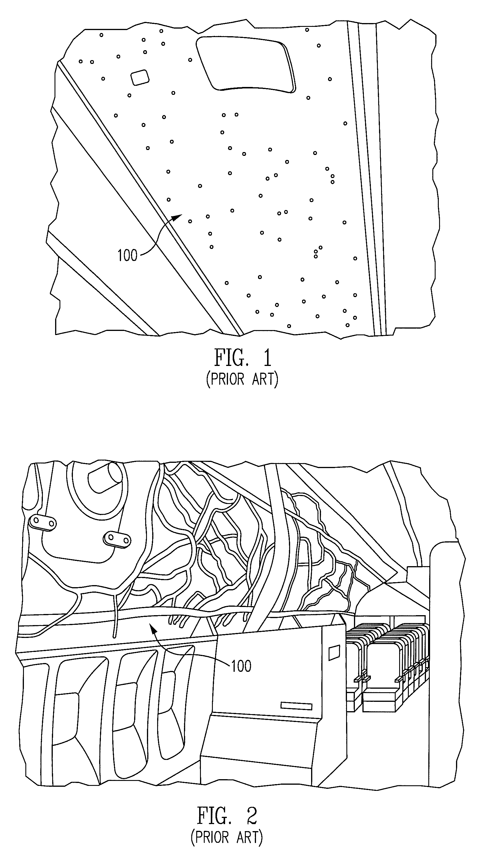
RELATED APPLICATIONS[0001]This is a continuation-in-part of U.S. patent application Ser. No. 11 / 848,467, filed Aug. 31, 2007, the entire disclosure of which is incorporated herein by reference.BACKGROUND[0002]This disclosure relates to interior lighting panels for passenger aircraft, in general, and in particular, to an improved aircraft ceiling mounted lighting panel adapted to display a starry nighttime sky effect.[0003]Passenger aircraft that operate over long distances during the night typically include interior lighting arrangements that provide substantially reduced ambient light so that passengers can sleep comfortably, but which is still bright enough to enable those passengers who choose not to sleep to move about the cabin safely. For example, as illustrated in FIG. 1, some models of current passenger jets incorporate ceiling panels 100 that incorporate light emitting diodes (LEDs) that are arranged so as to blink in random patterns against a gray or dark blue background, ...

Claims


Application Information

Patent Timeline
Patent Type & Authority Patents(United States)
IPC IPC(8): F21S4/00F21S8/02G09F13/08
CPCB60Q3/0203B60Q3/025B60Q3/0283F21K9/00B60Q2500/10F21W2121/008F21Y2101/02F21Y2115/10B60Q3/51B60Q3/43B60Q3/745B60Q3/54
Inventor MARSHALL, JOSEPH A.NELSON, GREGORY W.MITCHELL, BRADLEY J.PRINCE, BROCK J.
Owner THE BOEING CO
Learn More