
Mounting structure for motor controller of heat-dissipating device

a technology of heat dissipation device and mounting structure, which is applied in the direction of structural association, dynamo-electric machines, supports/enclosements/casings, etc., can solve the problems of increasing fabrication cost, complicated circuit of above conventional mounting methods for hall sensors, and reducing the layout area on the pcb, so as to improve the mounting structure and reduce the cost and fabrication complexity.

Active Publication Date: 2007-11-06
DELTA ELECTRONICS INC
View PDF17 Cites 5 Cited by
  • Summary
  • Abstract
  • Description
  • Claims
  • Application Information

AI Technical Summary

Benefits of technology

The invention provides an integrated motor controller for a DC brushless motor that replaces the conventional complicated PCB. It also provides an improved mounting structure for the motor controller that reduces cost and fabrication complexity. The invention also provides a heat-dissipating device with a container to secure the motor controller and a frame with a chassis, stator, and rotor surrounding the stator coupling thereof. The motor controller has a plurality of pins with broadened contacts to which a plurality of wires of an external device are connected. The invention simplifies the control and driving of the DC brushless motor.

Problems solved by technology

The circuit of the above conventional mounting methods for Hall sensors is, however, complicated, which reduces available layout area on the PCB and increases fabricating cost.
The complicated layout on the PCB also increases impedance and causes considerable power loss.
Moreover, since the Hall sensors are not consistently bent to predetermined angles during fabrication, their position corresponding to the position of the magnetic poles will be easily displaced resulting from externally careless collision.

Method used


Image

  • Mounting structure for motor controller of heat-dissipating device
  • Mounting structure for motor controller of heat-dissipating device
  • Mounting structure for motor controller of heat-dissipating device

Examples


first embodiment

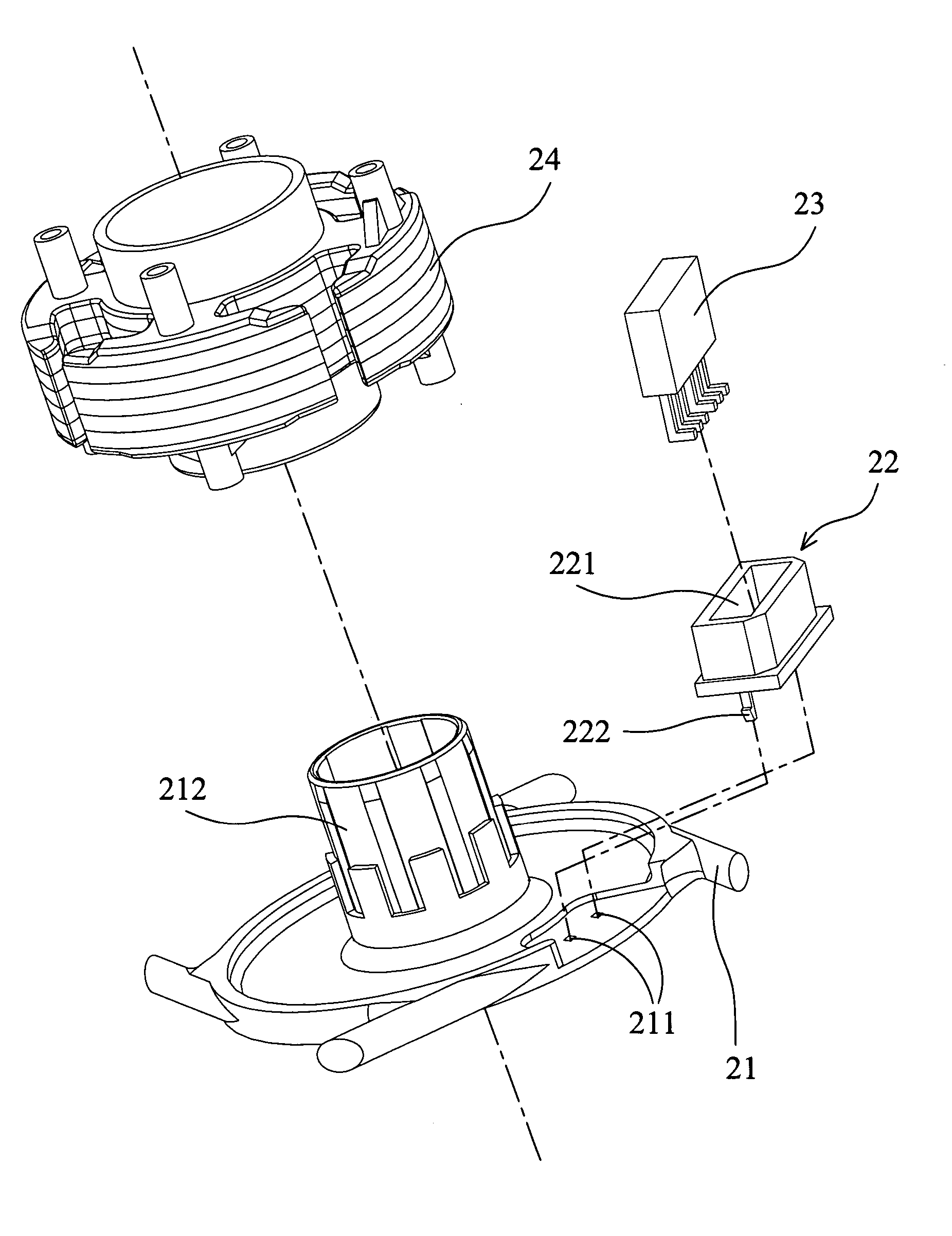
[0028]FIG. 2 shows a mounting structure for the motor controller of a DC brushless motor in the invention. In FIG. 2, the container 22 is substantially square with a slot 221 in the central portion thereof. The slot 221 can be shaped according to the profile and size of the motor controller 23 to contain the motor controller 23 therein. The container 22 has two hooks 222 on the either side of the bottom surface to engage holes 211 on the chassis 21, so as to fix the container 22 thereon. Alternatively, the container 22 can also be adhered to the chassis 21.

[0029]After the stator 24 is assembled on the sleeve 212 of the chassis 21, the relative position of the stator 24 and the motor controller 23 contained in the container 22 can be determined. Thus, through such a mounting design, the relative position between the motor controller 23 and the stator 24 will not be shifted due to the collision from an external force.

[0030]FIG. 3 shows another mounting structure for the motor controll...

third embodiment

[0031]Another mounting structure for the motor controller is provided in FIG. 4. The stator 44 includes two cover portions 441 and a plurality of stator plates sandwiched therebetween. The container 42 for the motor controller 43 of the third embodiment can be disposed on a cover portion 441 of the stator 44. Furthermore, the container of this structure includes two positioning pillars 42 similar to those in FIG. 3, disposed on the lower cover portion 441 between two neighboring magnetic poles, allowing assembly of motor controller 43 therebetween. Finally, the rotor 45 and stator 44 are sequentially telescoped to the sleeve 412 of the chassis 41. Thus, the motor controller 43 can detect phase change of the magnetic field and control the motor of the fan.

[0032]The method of connecting the pins of the motor controller and the wires is shown in FIG. 5. The pins 531 of the motor controller 53 can be designed with broadened ends, forming contacts 532 with larger soldering area for the w...


PUM


Abstract

A modified mounting structure for a heat-dissipating device. The heat-dissipating device has a motor and a seat with a slot mounted on a base or the cover portion of a stator thereof. The seat secures a motor controller of the heat-dissipating device detecting phase changes of the magnetic poles of the motor. The structure of a heat-dissipating device reduces required components, manufacturing cost and assembly time, and the control circuit is greatly simplified.

Description

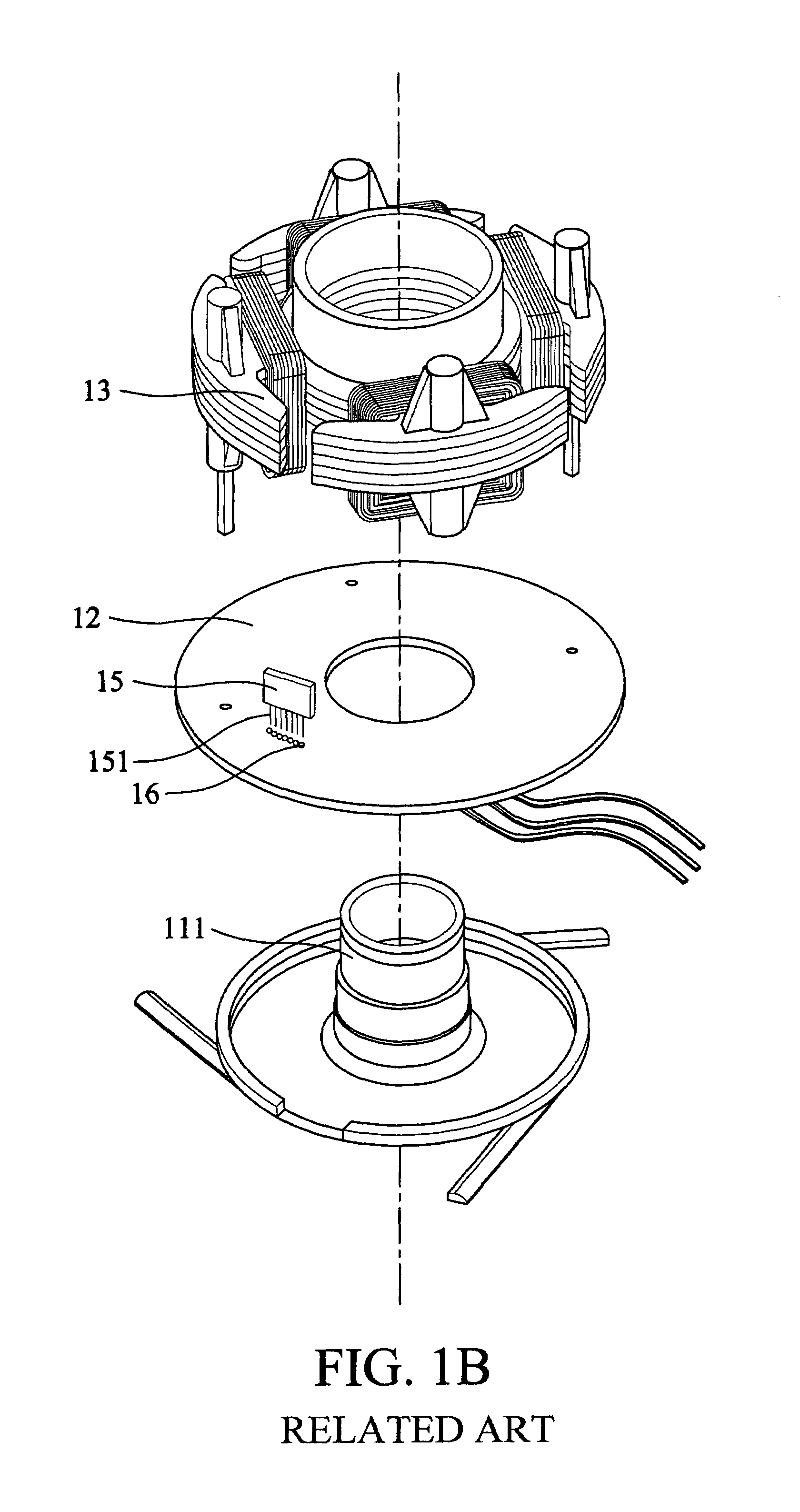
[0001]This Nonprovisional application claims priority under 35 U.S.C. § 119(a) on patent application Ser. No(s). 092214276 filed in TAIWAN on Aug. 6, 2003, the entire contents of which are hereby incorporated by reference.BACKGROUND OF THE INVENTION[0002]1. Field of the Invention[0003]The present invention relates to a container for a motor controller of a heat-dissipating device, and in particular to a motor controller and a container for a DC brushless motor in a heat-dissipating device.[0004]2. Description of the Related Art[0005]DC brushless motors are used in many electronic devices, such as heat-dissipating fans. FIG. 1A shows a conventional fan using a DC brushless motor. In FIG. 1A, the fan includes a frame 11, a printed circuit board 12 (PCB), a stator 13, and a rotor 14. When assembling the fan, the PCB 12, stator 13 and rotor 14 are sequentially assembled to a sleeve 111 on a base portion of the frame 11.[0006]Unlike a conventional DC motor, a brushless DC motor includes ...

Claims


Application Information

Patent Timeline
Patent Type & Authority Patents(United States)
IPC IPC(8): H02K7/00H02K5/22H02K7/14H02K11/00
CPCH02K5/22H02K29/08H02K7/14
Inventor LIU, CHENG-CHIEHCHOU, YI-FANGLIN, TSU-LIANGTSAI, MING-SHILIN, KUO-CHENG
Owner DELTA ELECTRONICS INC
Learn More