Lens fabrication apparatus and lens fabrication method using the same

a technology of fabrication apparatus and lens, which is applied in the direction of manufacturing tools, instruments, applications, etc., can solve the problems of inability to avoid the generation of voids in the molded lens, the flow of molding materials in the filling of the lens mold is not always uniform, and the dimensional accuracy of the lens may be degraded, so as to reduce the generation of voids in the lens, enhance the dimensional accuracy of the lens, and reduce the time and fabrication costs

Inactive Publication Date: 2013-02-28
SAMSUNG ELECTRONICS CO LTD
View PDF2 Cites 5 Cited by
  • Summary
  • Abstract
  • Description
  • Claims
  • Application Information

AI Technical Summary

Benefits of technology

The present invention is a lens fabrication apparatus and method that improves the shape of lenses and reduces voids while reducing fabrication time and costs. The apparatus achieves these improvements by using a specific process.

Problems solved by technology

However, the coupling using the adhesion method may have a problem, in which dimensional accuracy may be degraded due to weak adhesive strength between the lens and the package.
Also, according to the adhesion method, the package and the lens are substantially bonded while exposed in the air, therefore making it impossible to avoid the generation of voids in the molded lens.
A flow of the molding material when filling the lens mold is not always uniform.
Namely, due to the irregular flow of the molding material filling the lens mold, and a phenomenon in which air is drawn into a gap between an injection nozzle and the lens mold, air is captured within the molding material, resulting in a failure to prevent the generation of voids.
The presence of voids brings about defective hardening of the molding material filling the lens mold, and causes a direct reduction in both the uniformity of light emitted through a completed lens and light efficiency.

Method used


Image

  • Lens fabrication apparatus and lens fabrication method using the same
  • Lens fabrication apparatus and lens fabrication method using the same
  • Lens fabrication apparatus and lens fabrication method using the same

Examples


Embodiment Construction

[0058]Embodiments of the present invention will now be described in detail with reference to the accompanying drawings. The invention may, however, be embodied in many different forms and should not be construed as being limited to the embodiments set forth herein. Rather, these embodiments are provided so that this disclosure will be thorough and complete, and will fully convey the scope of the invention to those skilled in the art. In the drawings, the shapes and dimensions of elements may be exaggerated for clarity, and the same reference numerals will be used throughout to designate the same or like components.

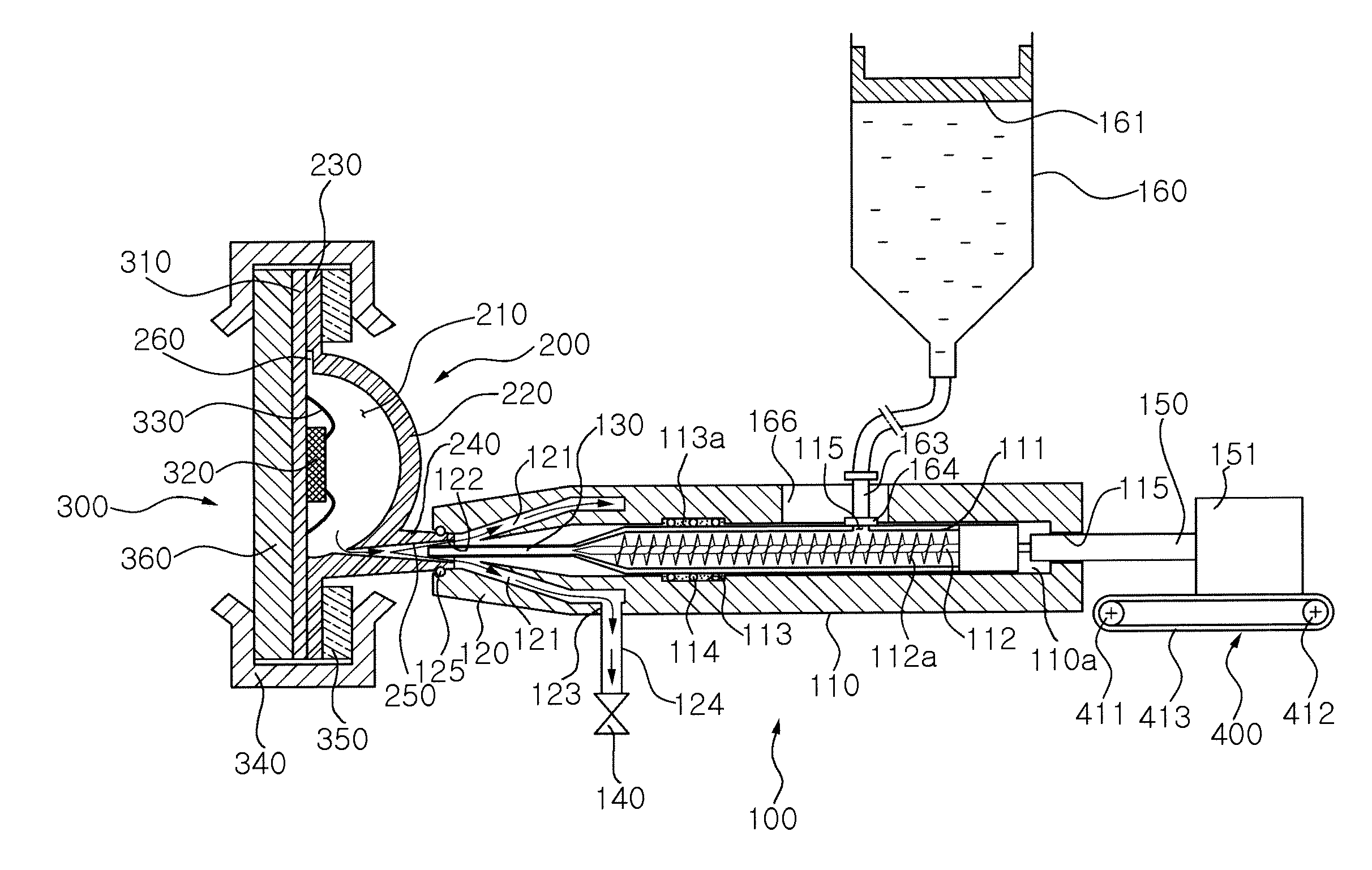
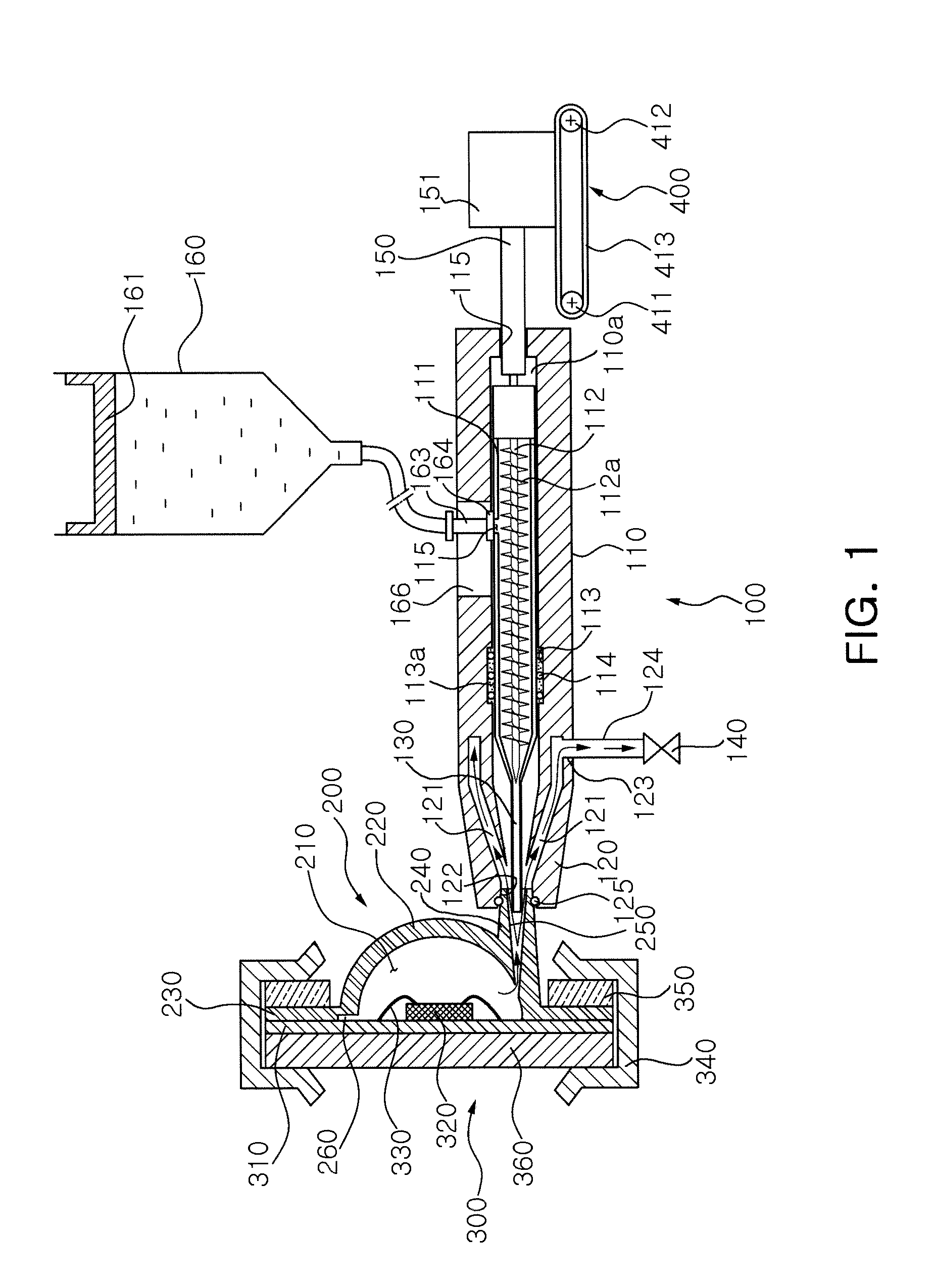
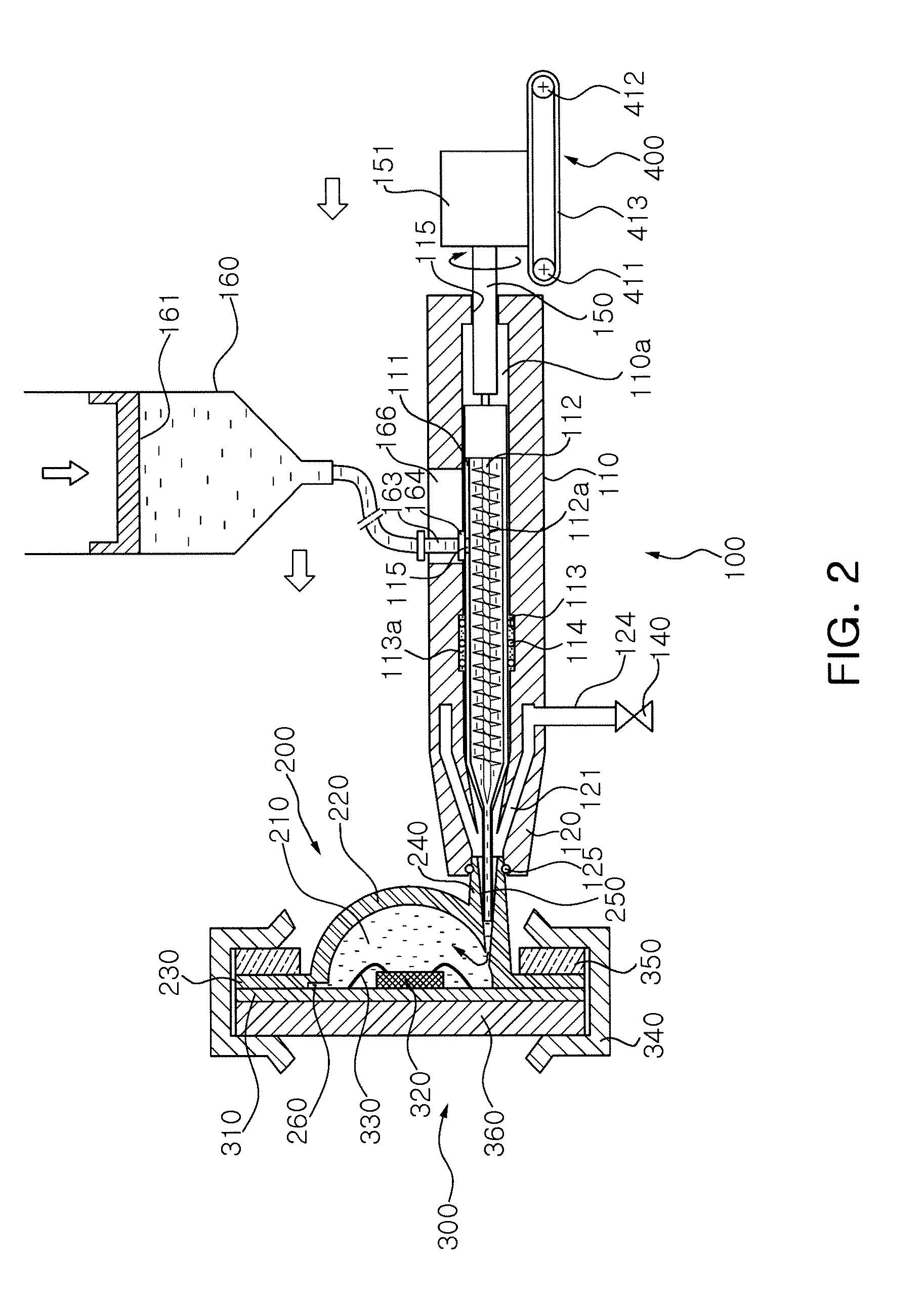
[0059]A lens fabrication apparatus according to an embodiment of the present invention will now be described with reference to FIGS. 1 and 2.

[0060]The lens fabrication apparatus according to an embodiment of the present invention includes a lens mold 200 having a connection portion 240 formed at one side thereof and disposed on a light emitting unit, and a vacuum forming u...


PUM

PropertyMeasurementUnit
Vacuumaaaaaaaaaa
Lightaaaaaaaaaa

Abstract

A lens fabrication apparatus includes: a lens mold having a connection portion formed on one side thereof and disposed on a light emission surface of a light emitting unit; and a vacuum forming unit discharging air from within the lens mold to the outside through the connection portion or injecting a material into the lens mold through the connection portion.

Description

CROSS-REFERENCE TO RELATED APPLICATIONS[0001]This application claims the priority of Korean Patent Application No. 10-2011-0086827 filed on Aug. 30, 2011, in the Korean Intellectual Property Office, the disclosure of which is incorporated herein by reference.BACKGROUND OF THE INVENTION[0002]1. Field of the Invention[0003]The present invention relates to a lens fabrication apparatus and a lens fabrication method using the same.[0004]2. Description of the Related Art[0005]In general, light emitting devices are fabricated in the form of a package including (one or more) light emitting diodes (LEDs) mounted therein, and LED packages are generally fabricated by using a substrate or a reflector pre-mold.[0006]Here, in order to cover the LEDs to protect them and to enhance the optical characteristics of the packages, e.g., to increase light emission efficiency within a certain orientation angle, an optical unit, such as a lens, or the like, is provided in an upper portion of an LED package...

Claims


Application Information

Patent Timeline
IPC IPC(8): G02B1/12B29C45/34
CPCB29C45/34B29C45/14336B29L2011/0016B29C51/10B29D11/00
Inventor YOO, CHEOL JUN
Owner SAMSUNG ELECTRONICS CO LTD
Why Eureka
Try Eureka