
Method and system for out of band predistortion linearization

a linearization and out-of-band technology, applied in the field of linearization methods for radio transmitters, can solve the problems of increasing bit error rate, disturbing adjacent radio channels, increasing etc., and achieves the effect of facilitating and simplifying design and application, reducing the power efficiency of amplifiers, and improving the accuracy of compensation

Inactive Publication Date: 2010-12-07
ZTE CORP
View PDF19 Cites 18 Cited by
  • Summary
  • Abstract
  • Description
  • Claims
  • Application Information

AI Technical Summary

Benefits of technology

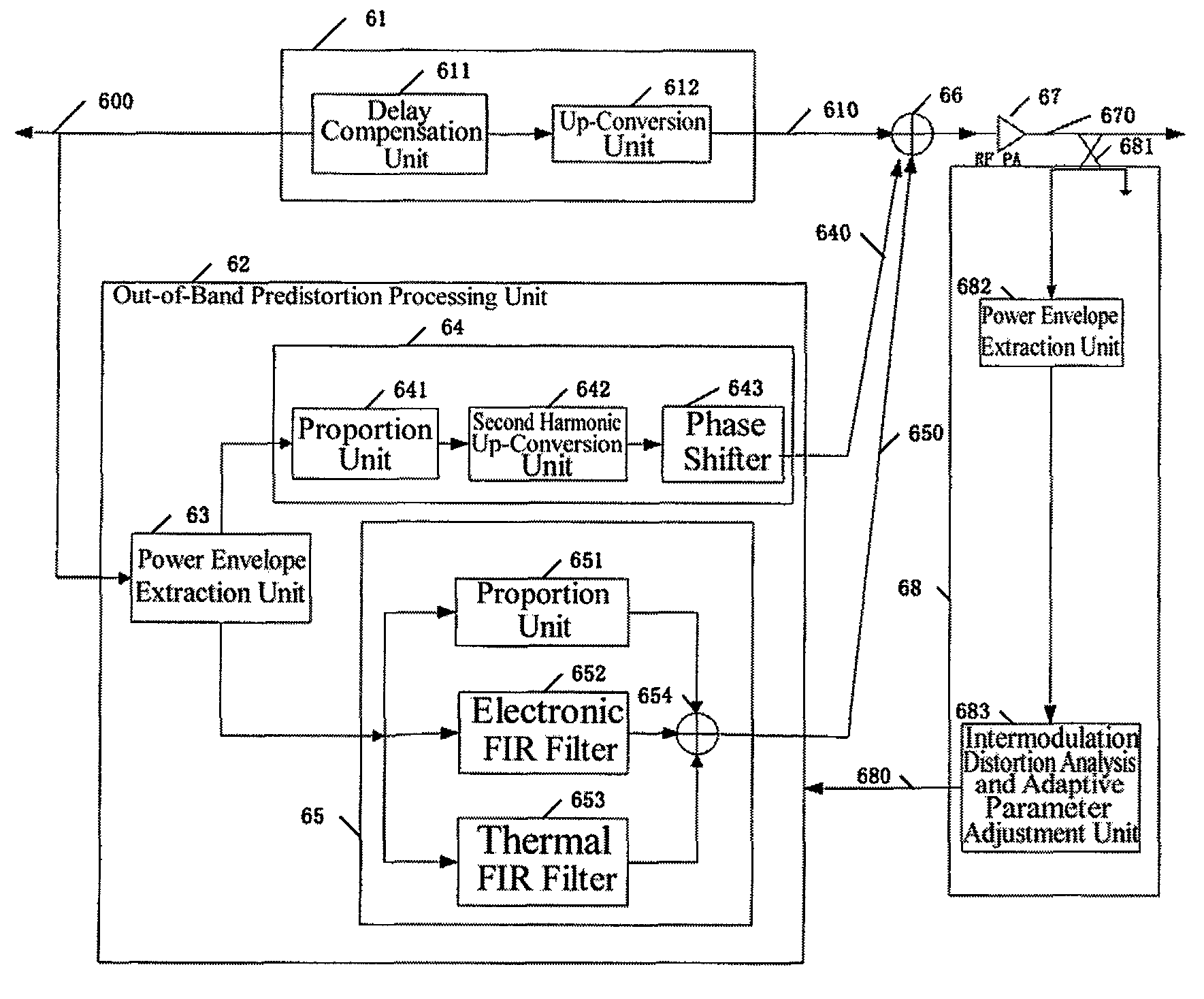
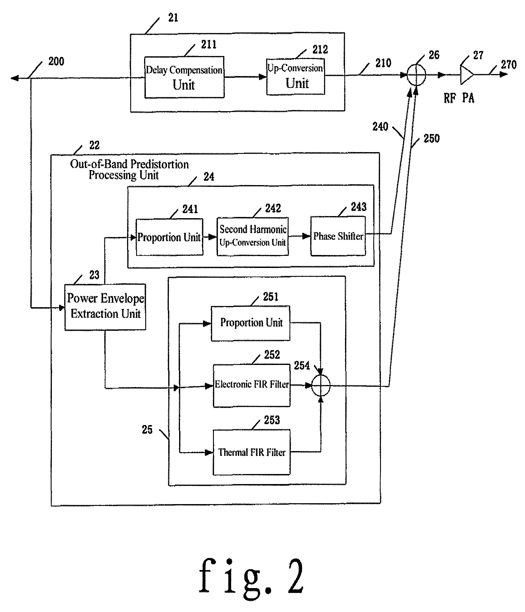
The present invention provides a method and system for out-of-band predistortion linearization in a wireless environment. The method involves dividing the inputted base band or IF signal into in-band and out-of-band signal branches, processing each branch separately, and adding the two processed signals together as the input of the RF power amplifier. The out-of-band signal is pre-compensated by a second harmonic injection and an envelope injection, which enhances the linearization performance of the predistortion technique. The system includes an in-band signal processing part, an out-of-band predortion processing unit, and a signal adder. The invention improves the linearization performance of the predistortion technique and enhances the linearization performance of the RF power amplifier.

Problems solved by technology

In recent years, with the rapid development of wireless communication throughout the world, resources of radio frequency spectrum becomes more and more insufficient.
Since both the phase and amplitude of linear modulation signals carry useful information, any nonlinear amplification of these signals will increase bit error rate and disturb adjacent radio channels.
However, this power back-off technique has the following obvious disadvantages: firstly, the improvement of linearity according to this method is at expense of power efficiency of the amplifier, which means that the power output capability of the amplifier is not fully utilized, therefore decreasing the power efficiency of the amplifier and increasing the cost; secondly, the low power efficiency means that most power is released in the form of heat, bringing a huge pressure on the ventilation and heat dispersion system of the whole base station; finally, an amplifier of low power efficiency needs an electrical power system with larger capacity, which is also an important factor for the increased cost of transmitter.
But both these two techniques have limitations: the main problem of the feed-forward technique lies in poor power efficiency, complicated structure and high cost of the RF power amplifier; while the feedback technique has the problem of unstable loop and limited linearization bandwidth.
Therefore, neither of the above two techniques can offer highly linear amplification on wide frequency band with the power efficiency required by next generation mobile communication base station.
However, if without special measures, both the linearization bandwidth and linearization capacity that can be provided by the digital predistortion linearization method will be very limited.
The reasons are: on one hand, this predistortion technique implicates an unavoidable paradox that, in order to compensate part of non-linearization, the amplifier is set in a more nonlinear state resulting in impossibility of compensation in some conditions, therefore the compensation effect has a close relation with back off of the amplifier and peak-to-average ratio of the input signal; on the other hand, the amplifier has memory effect which greatly influences the predistortion effect.
However, in this method, in order to compensate the AM-PM distortion, part of the predistortion has to be processed in band, so the system is required to provide base band I, Q signals respectively, which will be inconvenient in some application environments, especially in wireless communication field.
The reasons are: compared with separated I, Q information streams in digital base band, in the case of radio frequency (RF) or intermediate frequency (IF), the I, Q signals carrying the I, Q information streams are compound I, Q signals that have been modulated, therefore in some digital predistortion systems required to provide independent I, Q signals respectively, an extra I, Q demodulation process will be needed; however, most RF power amplifiers are produced by particular manufactures, so sometimes it is inconvenient to modify the design of the digital base band for adding the predistortion function.

Method used


Image

  • Method and system for out of band predistortion linearization
  • Method and system for out of band predistortion linearization
  • Method and system for out of band predistortion linearization

Examples


Embodiment Construction

[0034]Preferred embodiments of the present invention will be described in further detail with reference to the accompanying drawings.

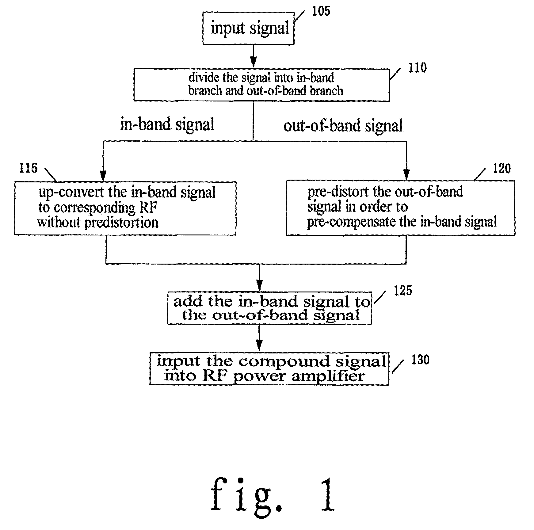
[0035]FIG. 1 is a flow chart of a method for out-of-band predistortion linearization in accordance with an embodiment of the present invention. Steps of the method will be described in detail with reference to FIG. 1.

[0036]As shown in FIG. 1, firstly in step 105, receiving the base band or IF signals to be input into the RF power amplifier.

[0037]step 110, directly dividing the received base band or IF signals into two branches, i.e., an in-band signal branch and an out-of-band signal branch, thus, the original base band or IF signals being divided into a branch of in-band signals and a branch of out-of-band signals.

[0038]step 115, processing the in-band signals, directly up-converting the in-band signals to a corresponding radio frequency, which means the in-band signals are not processed for predistortion; in this step, first performing delay compensa...


PUM


Abstract

The present invention discloses a method and a system for out-of-band predistortion linearization, comprising steps of: dividing base band inputted or intermediate frequency signal into an in-band signal branch and an out-of-band signal branch; processing the in-band signal to form RF (Radio Frequency) signal; processing the out-of-band signal to form out-of-band predistortion signal for pre-compensating the in-band signal; adding the in-band signal with the out-of-band predistortion signal, and taking the result as the input of RF power amplifier. The present invention compensates the nonlinear distortion of the RF power amplifier by a way of out-of-band compensating signal in a wireless communication environment, thereby avoiding the limitation of improving performance of conventional predistortion method, and solving the limitation of bandwidth and capability of the predistortion system caused by memory effect.

Description

RELATED APPLICATIONS[0001]The present application is based on, and claims priority from, International Application Number PCT / CN2004 / 001490, filed Dec. 21, 2004, the disclosure of which is hereby incorporated by reference herein in its entirety.TECHNICAL FIELD[0002]The present invention relates to a linearization method for radio transmitter and a system thereof, and more particularly to a method and a system adopting out-of-band predistortion linearization technique to improve the linearity of the radio transmitter.BACKGROUND OF THE INVENTION[0003]In recent years, with the rapid development of wireless communication throughout the world, resources of radio frequency spectrum becomes more and more insufficient. In order to utilize the finite spectrum resources effectively, many wireless communication systems have adopted linear modulation which has a high rate of spectrum utilization. Since both the phase and amplitude of linear modulation signals carry useful information, any nonli...

Claims


Application Information

Patent Timeline
Patent Type & Authority Patents(United States)
IPC IPC(8): H04B1/04
CPCH03F1/3241H03F1/3294H04L27/368H03F2201/3224
Inventor LIU, XIAOWEI
Owner ZTE CORP
Learn More