
Shake detection apparatus and shake detection method

a technology of shake detection and shake compensation, which is applied in the direction of color television details, television systems, instruments, etc., can solve the problem of reducing the shake compensation effect of low-frequency shaking during panning

Inactive Publication Date: 2010-12-07
FUJIFILM CORP
View PDF9 Cites 1 Cited by
  • Summary
  • Abstract
  • Description
  • Claims
  • Application Information

AI Technical Summary

Benefits of technology

The solution effectively removes swing-back components, maintaining accurate shake detection and compensation during panning, thereby preventing misidentification of swing-back as actual shakes and ensuring optimal camera shake compensation.

Problems solved by technology

However, the technique described in Japanese Patent Application Laid-Open No. 11-284902 has the disadvantage that although the swing-back phenomenon is reduced, the shifting of the cut-off frequency to the high-frequency side results in reduced shake compensation effect for low-frequency shaking during panning.

Method used


Image

  • Shake detection apparatus and shake detection method
  • Shake detection apparatus and shake detection method
  • Shake detection apparatus and shake detection method

Examples


first embodiment

[0096]Next, operation of the swing-back suppressor 74 of the digital camera 1 according to a first embodiment will be described. FIG. 8 is a block diagram showing a circuit configuration inside the swing-back suppressor 74.

[0097]The swing-back suppressor 74 includes an integrator 75, determination unit 76, switch 77, and adder 78. As described above, the angular velocity signal converted into a digital signal by the A / D converter 53 is inputted in the swing-back suppressor 74.

[0098]FIG. 9A shows an output signal of the X gyro sensor 50 when the digital camera 1 is stationary (static) (up to t0), panned in the +X direction (t0 to t2), stationary (t2 to t4), panned in the −X direction (t4 to t6), and stationary (from t6) in sequence.

[0099]The output signal of the X gyro sensor 50 has its low-frequency component removed by the high-pass filter 51. Then, the output signal is amplified by the amplifier 52, converted into a digital signal by the A / D converter 53, and inputted in the swing...


PUM


Abstract

A shake detection technique which does not mistakenly detect a swing-back component at the end of panning as a shake is provided. A shake detection apparatus includes: a sensor which detects velocity or angular velocity; a high-pass filter which removes a low-frequency component from an output signal of the sensor; a shake detection device which detects shake of an apparatus body based on an output signal from the high-pass filter; a determination device which determines whether the output signal of the high-pass filter contains a swing-back component outputted when a shake continued in one direction stops; and a removal device which removes the swing-back component from the output signal of the high-pass filter based on a determination result of the determination device.

Description

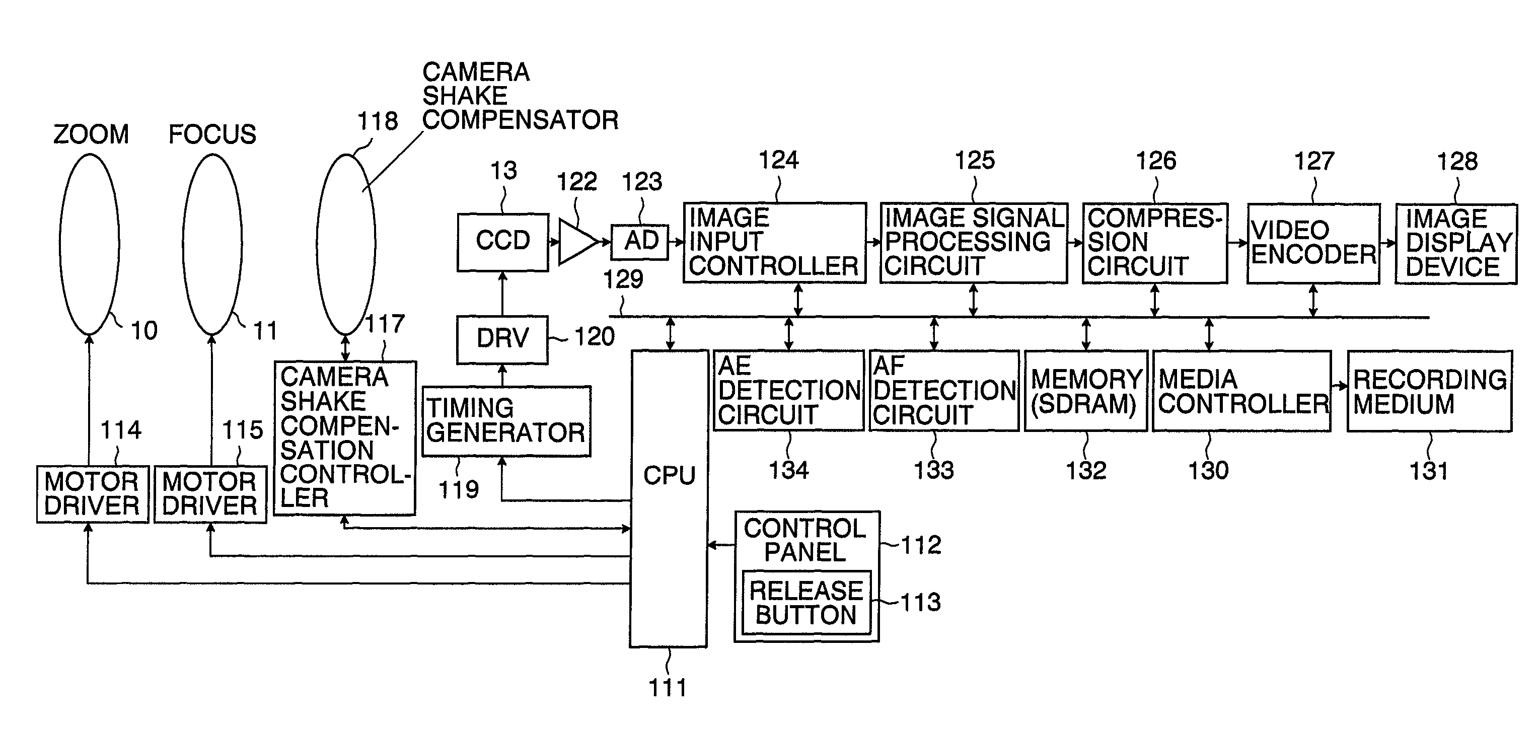
BACKGROUND OF THE INVENTION[0001]1. Field of the Invention[0002]The present invention relates to a shake detection apparatus and shake detection method, and more particularly, to a shake detection apparatus and shake detection method which detect shake by removing a low-frequency component from an output signal of a gyro sensor using a high-pass filter.[0003]2. Description of the Related Art[0004]A mechanism used in an image pickup apparatus such as a camera to compensate for camera shake caused by a photographer is known. Such a camera shake compensation mechanism compensates for shake by detecting angular velocity using a gyro sensor, calculating an amount of shake of the image pickup apparatus from the detected angular velocity, and moving a part of an image pickup unit such as a taking lens or image sensor in a plane perpendicular to a photographic optical axis in such a way as to cancel off the calculated amount of shake. An output signal from a gyro sensor contains unnecessary...

Claims


Application Information

Patent Timeline
Patent Type & Authority Patents(United States)
IPC IPC(8): G03B17/00H04N5/228H04N23/40
CPCG03B17/00
Inventor MIZUTA, TOMOYUKI
Owner FUJIFILM CORP
Learn More