
Multiple-wavelength tunable laser

a laser and multi-wavelength technology, applied in the direction of laser details, optical resonator shape and construction, electrical equipment, etc., can solve the problems of complicated replacement and disposal, short life of dyes, and most present serious drawbacks, and achieve the effect of simple and safe manner

Inactive Publication Date: 2010-12-07
NASA
View PDF19 Cites 5 Cited by
  • Summary
  • Abstract
  • Description
  • Claims
  • Application Information

AI Technical Summary

Benefits of technology

The present invention provides a tunable laser that can produce multiple wavelengths in a variety of spectral regions. The laser resonator includes dispersion optics that separate generated laser pulses into processed laser pulses with different wavelengths. The laser resonator is defined at one end by mirrors that reflect the first and second wavelengths and at the other end by an output mirror that partially reflects and partially transmits the first and second wavelengths. The length of the resonator is a function of the length of the first resonator. The technical effects of this invention include the ability to produce multiple wavelengths in a variety of spectral regions in a simple and safe manner.

Problems solved by technology

Although there are some lasers that can possibly address the needed spectral regions, most present serious drawbacks.
However, the dyes have a short lifetime and must be replaced frequently.
Furthermore, some of the dyes and solvents are carcinogenic thereby complicating their replacement and disposal.
In addition, the high-gain and short upper laser level lifetime lasers associated with dye lasers makes it difficult for these lasers to provide good beam quality.
However, the halogens corrode the laser chamber and simultaneously deplete themselves.
Halogens also pose a health hazard.
These discharges cause reliability concerns and may affect other electronic instruments.

Method used


Image

  • Multiple-wavelength tunable laser
  • Multiple-wavelength tunable laser
  • Multiple-wavelength tunable laser

Examples


Embodiment Construction

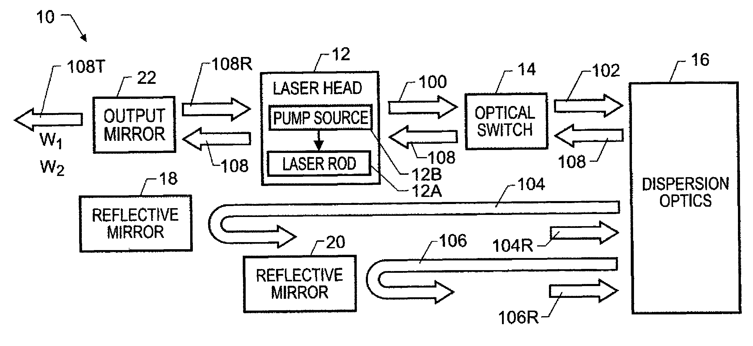
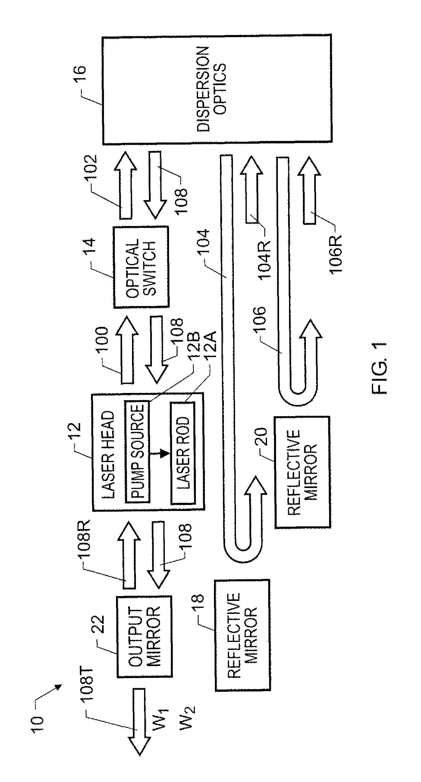
[0017]Referring now to the drawings and more particularly to FIG. 1, a multiple-wavelength tunable laser in accordance with an embodiment of the present invention is show and is referenced generally by numeral 10. In the illustrated embodiment, tunable laser 10 simultaneously produces synchronous laser pulses at two distinct wavelengths W1 and W2 that can be in the infrared spectrum. However, as will be apparent to one of ordinary skill in the art, the principles of the present invention can be readily extended to simultaneously produce synchronous laser pulses at more than two wavelengths.

[0018]Tunable laser 10 includes a laser head 12 and a number of optical components that define a laser resonator. Laser head 12 typically includes a rod 12A of lasing material and a pump source 12B (e.g., a flash lamp) as would be understood in the art. For example, in terms of generating laser pulses at multiple infrared wavelengths, rod 12A is typically a neodymium-doped yttrium aluminum garnet ...


PUM


Abstract

A tunable laser includes dispersion optics for separating generated laser pulses into first and second wavelength pulses directed along first and second optical paths. First and second reflective mirrors are disposed in the first and second optical paths, respectively. The laser's output mirror is partially reflective and partially transmissive with respect to the first wavelength and the second wavelength in accordance with provided criteria. A first resonator length is defined between the output mirror and the first mirror, while a second resonator length is defined between the output mirror and the second mirror. The second resonator length is a function of the first resonator length.

Description

[0001]Pursuant to 35 U.S.C. §119 the benefit of priority from provisional application 61 / 029,020, with a filing date of Feb. 15, 2008, is claimed for this non-provisional applicationORIGIN OF THE INVENTION[0002]The invention was made by employees of the United States Government and may be manufactured and used by or for the Government of the United States of America for governmental purposes without the payment of any royalties thereon or therefor.BACKGROUND OF THE INVENTION[0003]1. Field of the Invention[0004]This invention relates to tunable lasers. More specifically, the invention is a tunable laser that can simultaneously produce multiple synchronized laser beams at unique wavelengths using a single laser source.[0005]2. Description of the Related Art[0006]High-peak pulsed laser sources are needed at various wavelengths throughout the visible and ultraviolet region. Many applications also require a pulsed laser source to be tunable. Among the applications requiring tunable laser...

Claims


Application Information

Patent Timeline
Patent Type & Authority Patents(United States)
IPC IPC(8): H01S3/10H01S3/08H01S3/082
CPCH01S3/08H01S3/0809H01S3/0811H01S3/082H01S3/1123H01S3/0092
Inventor BARNES, NORMAN P.WALSH, BRIAN M.REICHLE, DONALD J.
Owner NASA
Learn More