
System for rotary drilling by electrical discharge

a technology of electrical discharge and rotary drilling, which is applied in the direction of drilling machines and methods, earth drilling and mining, construction, etc., can solve the problems of three patents suffering from a major weakness, slow progress of the technique, and supply of electric power to the electrodes

Inactive Publication Date: 2019-08-13
ITHPP
View PDF17 Cites 1 Cited by
  • Summary
  • Abstract
  • Description
  • Claims
  • Application Information

AI Technical Summary

Benefits of technology

The invention provides a drilling system by electrical discharge which allows operation of the downhole system to be controlled from the surface in a simple and safe manner, without any electrical connection with the surface. The invention is also fully compatible with standard drilling rig equipment as well as with conventional drilling procedures. The invention improves safety, reliability and performance. Additionally, the invention includes a second electrical slide switch at the electric drilling tool which prevents charging of the pulse generator capacitors when the tool is in the "open" position. The rotation of the tool combines the mechanical effect of the passive electrodes with the effect of electrical discharges.

Problems solved by technology

However, these techniques suffer from slow forward progress in certain very hard or very abrasive geological formations.
However, these three patents suffer from a major weakness, namely the supply of electric power to the electrodes.
A means of transmission (by cable or other system) is therefore necessary to connect the surface to the borehole bottom, which leads to complexity and safety concerns.
All these documents present the same weakness: despite the presence of the pulse generator at the bottom of the borehole, the electric power required to supply it is provided by a cable from the surface.
However, the presence of a cable is a major obstacle which conflicts with the operational use of these systems.
However, these documents provide no details on the operation of the system in such a configuration, the first document being only on a non-rotating system.
In addition, for using a downhole electricity generator, these documents do not address the following three essential questions: control of the systems' operation from the surface, the safety of personnel in relation to the risk of high voltage when lifting out the drill string and compatibility with the use of a MWD (Measurement While Drilling) system which is almost routine these days, especially for oil drilling.

Method used


Image

  • System for rotary drilling by electrical discharge
  • System for rotary drilling by electrical discharge
  • System for rotary drilling by electrical discharge

Examples


Embodiment Construction

[0166]The invention is now described in more detail and in a non-limiting manner in the following description.

[0167]The invention can potentially be used in the following fields:[0168]oil sector (exploration and development of oil and / or gas deposits),[0169]mining sector (exploration drilling),[0170]geothermal sector (drilling of low or high enthalpy wells),[0171]civil engineering sector (geological assessment drilling, freeze-hole drilling, etc.).

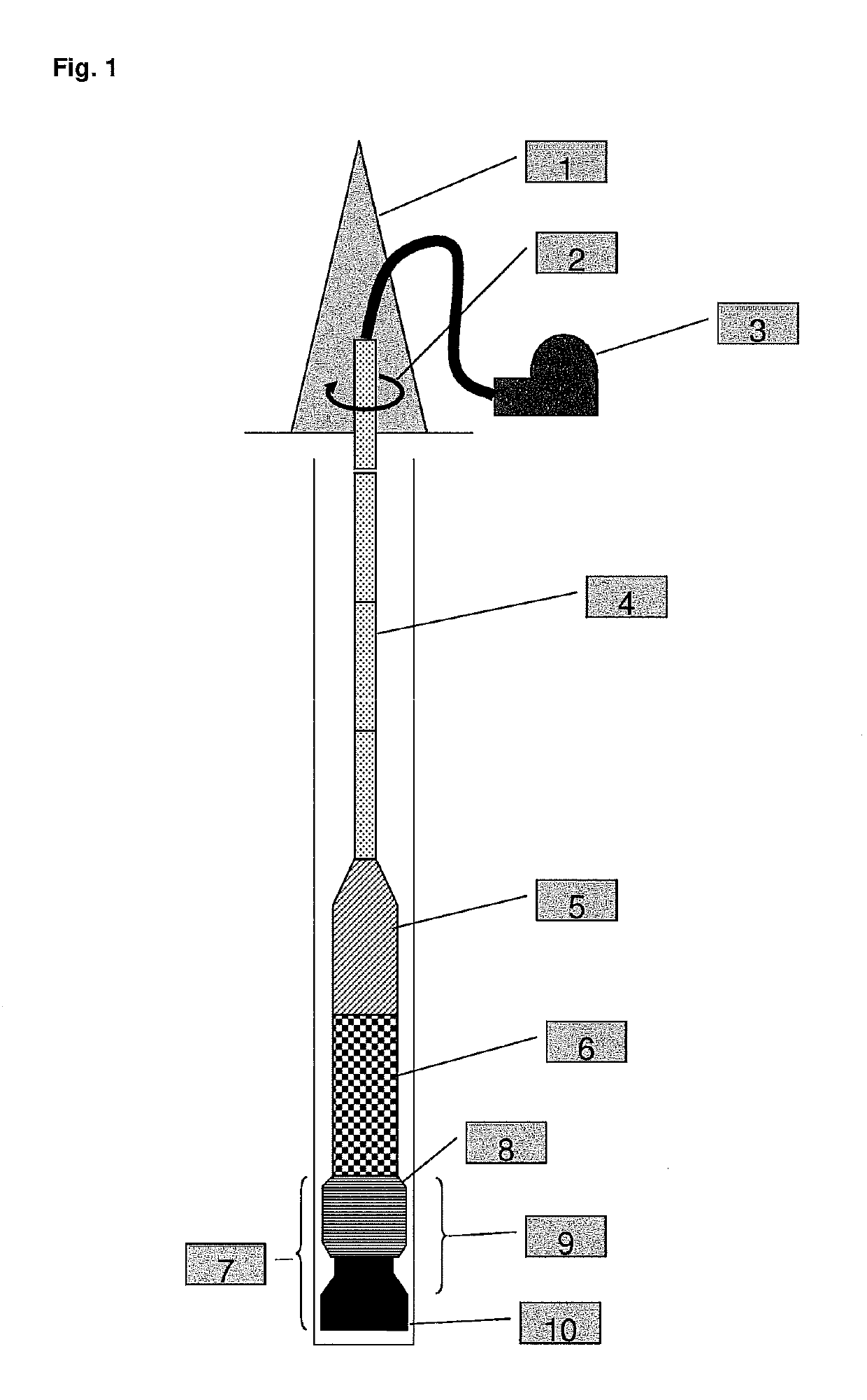
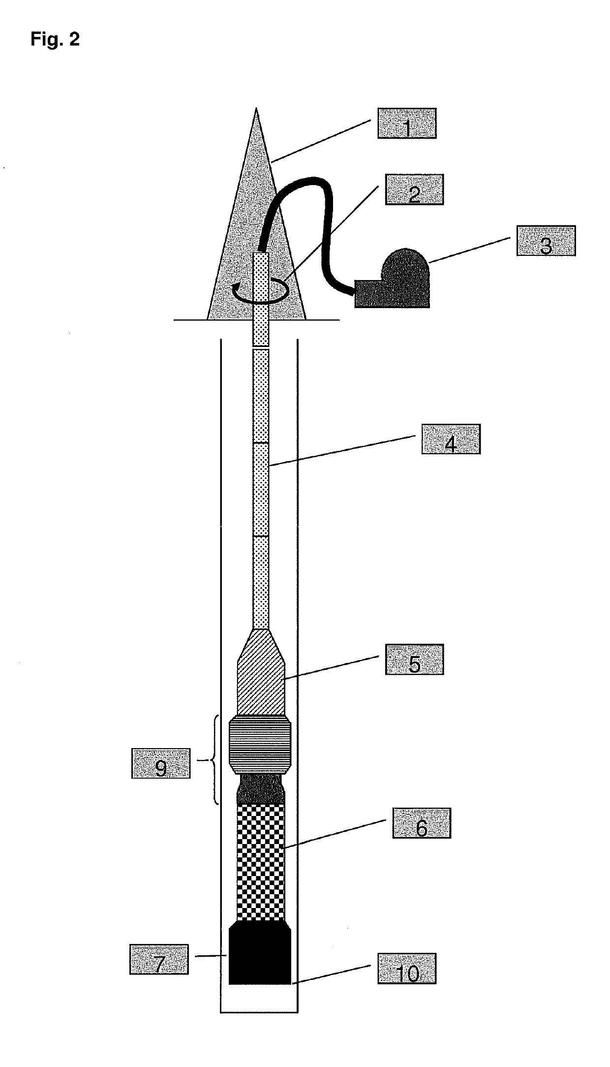
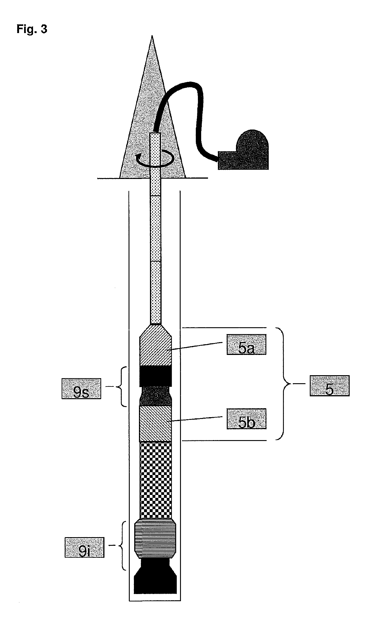
[0172]The downhole equipment presented is incorporated at the end of a standard drill string (an assembly of drill pipes and / or drill collars) requiring no special arrangement. It consists of the following elements:[0173]an electricity generator (5),[0174]a pulse generator (6),[0175]an electrical slide switch (9),[0176]an electric drilling tool (7).

[0177]Associated with this downhole equipment is a drilling rig equipped with a derrick, mast or any other handling system (1), a system for rotating the drill string (2) and pumps for injecting...


PUM


Abstract

A downhole device for rotary drilling is provided. The device includes a power generator installed at the end of a series of rods, a pulse generator which is mechanically and electrically connected to the electricity generator, an electric drilling tool, and an electrical sliding switch system.

Description

CROSS-REFERENCE TO RELATED APPLICATIONS[0001]This application is a § 371 national stage entry of International Application No. PCT / EP2015 / 053634, filed Feb. 20, 2015, which claims priority to French Patent Application No. 1451428 filed Feb. 21, 2014, the entire contents of which are incorporated herein by reference.FIELD OF THE INVENTION[0002]This invention relates to a device and a process of rotary drilling by electrical discharge and certain elements of the device.TECHNICAL BACKGROUND[0003]Conventional drilling techniques in the fields of Oil & Gas, Mining, Geothermal Energy, Civil Engineering and other activities consist of rotating a drilling tool downhole and at the same time applying a thrust force to it in the order of a few tons to several tens of tons. Rotation of the drilling tool is provided by rotation of the entire drill string from the surface (a system called “rotary drilling” in the art) or using a bottom hydraulic motor (turbodrilling). The drilling tools used are ...

Claims


Application Information

Patent Timeline
Patent Type & Authority Patents(United States)
IPC IPC(8): E21B7/15E21B41/00E21B3/00
CPCE21B7/15E21B41/0085E21B3/00E21B3/02
Inventor BAYOL, FRÉDÉRICDRAMANE, BONIGAUSSEN, JEAN-LOUISGOEPFERT, CHRISTOPHE
Owner ITHPP
Learn More