
Data reproduction method and apparatus, disk, and recording/reproduction apparatus, using PRML method

a data reproduction and optical disk technology, applied in the field of data reproduction methods, can solve the problems of difficult to achieve high density, frequent reproduction errors, and phase distortion of rf signals obtained from reflected ligh

Inactive Publication Date: 2010-11-09
RICOH KK
View PDF15 Cites 13 Cited by
  • Summary
  • Abstract
  • Description
  • Claims
  • Application Information

AI Technical Summary

Benefits of technology

The present invention provides a data reproduction method and apparatus for recording and reproducing data from an optical disk using a PRML detection method. The invention addresses limitations and disadvantages of existing methods and provides improvements in phase correction, clock extraction, and data decoding. The invention also includes an optical disk with recording marks arranged with a pitch less than a diffraction limit and a data recording / reproduction apparatus for recording and reproducing data with respect to the optical disk. The technical effects of the invention include improved data reproduction accuracy, reduced phase distortion, and improved data recording / reproduction apparatus.

Problems solved by technology

However, in a case of attempting to reproduce data recorded in the super-resolution optical disk by using the optical disk apparatus shown in Japanese Laid-Open Patent Application No. 2002-319137, phase distortion tends to occur in an RF signal obtained from reflected light.
This causes reproduction error to occur frequently.
However, since the method disclosed in Japanese Laid-Open Patent Application No. 1996-221839 does not use a PRML (Partial Response Maximum Likelihood) method which improves performance of decoding recording marks of small pitch, it is difficult to achieve high density even where super-resolution reproduction is used.
Optical aberration from tangential tilt may cause phase distortion of reproduction signals also for ordinary optical disks.
However, compared to the super-resolution method using magnetic transfer of a magneto-optical disk or asymmetry of a beam spot caused by tangential tilt, super-resolution reproduction causes a considerable phase distortion.
Therefore, it is difficult for adaptive signals to have clocks extracted beforehand for achieving the function of phase correction.
However, due to factors such as transparency of the polycarbonate material used in the optical disk, it is becoming more difficult to provide a laser beam with shorter wavelength or an objective lens with higher numeric aperture.
However, in a case of attempting to reproduce data recorded in the super-resolution optical disk by using the optical disk apparatuses shown in Patent Documents 1-4, phase distortion tends to occur in an RF signal obtained from reflected light.
This causes reproduction error to occur frequently.
Hence, it is difficult to increase data capacity with the optical disk apparatuses shown in Patent Documents 1-4.
The use of such optical disk apparatus is due to the growing difficulty of reading a single bit of digital data without encountering interference of a neighboring bit (intersymbol interference) along with the increase of recording density of the optical disk (recording medium) to which the digital data are recorded.
However, the reading system for reading data from the optical disk has a non-linear property owing to the principle of reading out signals by using light diffraction.
Such change in the position of the recording mark is caused by temperature interference during a data recording operation.
The asymmetric property and the non-linear component of the RF signal make it difficult to increase the density of recording data to the optical disk.
However, since the maximum likelihood estimate bit length and the non-linear compensation length is the same in the method disclosed in the Non-Patent Document 1, the non-linear compensation effect is limited in a case where the non-linear compensation length is short with respect to the length of the beam spot on the optical disk (recording medium) (i.e. in a case of high density recording).
Particularly, the non-linear compensation effect is insufficient during reproduction of data from a high resolution optical disk in which data are recorded with a density greater than the diffraction limit of the optical system or during generation of aberration (e.g., coma-aberration, astigmatism) where the beam spot diameter is increased.
However, since the method disclosed in Patent Document 5 requires the maximum likelihood estimation to be performed with the same range as the non-linear compensation bit length, the circuit size becomes considerably large as the non-linear compensation range is increased.
This causes the reproduction apparatus to become expensive.
Therefore, this method is insufficient for achieving a significant increase of data capacity.
However, the symmetrically shaped partial response characteristics of Patent Document 7 are far from matching with the characteristics of the analog reproduction signals read out by irradiating an asymmetric beam spot to the super resolution optical disks disclosed in Patent Document 1-4.
This results in a problem of inconsistency (mismatch) between the characteristics of the reproduction system and the partial response characteristics.
This leads to increase of bit error rate.

Method used


Image

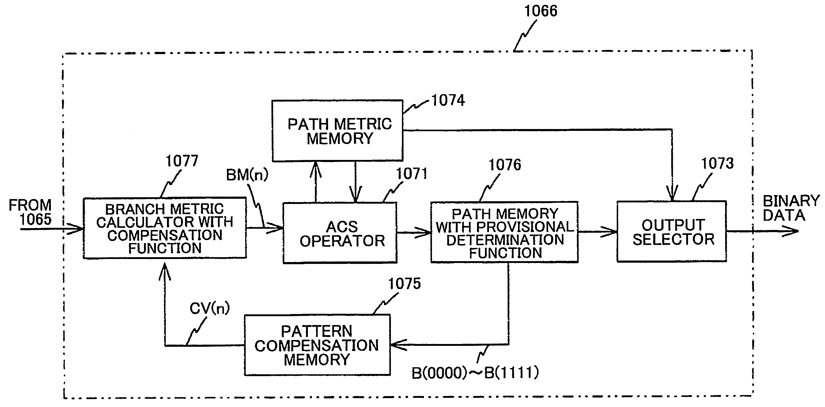
  • Data reproduction method and apparatus, disk, and recording/reproduction apparatus, using PRML method
  • Data reproduction method and apparatus, disk, and recording/reproduction apparatus, using PRML method
  • Data reproduction method and apparatus, disk, and recording/reproduction apparatus, using PRML method

Examples


Embodiment Construction

[0105]In the following, embodiments of the present invention are described with reference to the accompanying drawings.

[Section 1]

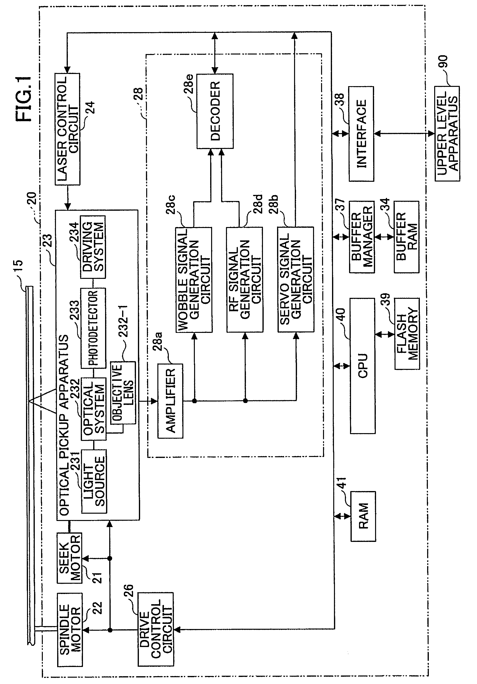
[0106]FIG. 1 is a schematic diagram showing an optical disk apparatus 20 according to an embodiment of the present invention.

[0107]In FIG. 1, the optical disk apparatus 20 includes, for example, a spindle motor 22 for rotating an optical disk 15, an optical pickup apparatus 23, a seek motor 21 for driving the optical pickup apparatus 23 in a radial direction, a laser control circuit 24, a drive control circuit 26, a reproduction signal processing circuit 28, a buffer RAM 34, a buffer manager 37, an interface 38, a flash memory 39, a CPU 40, and a RAM 41. It is to be noted that the arrows illustrated in FIG. 1 indicate the flow of representative signals and data and do not indicate the entire connection relationship of each of the blocks. The optical disk 15 according to an embodiment of the present invention is a super-resolution optical disk for enabling...


PUM

PropertyMeasurementUnit
diameteraaaaaaaaaa
lengthaaaaaaaaaa
wavelengthaaaaaaaaaa

Abstract

A data reproduction apparatus for reproducing recorded data from an optical disk by using a PRML detection method is disclosed that includes an optical head including a light source, an optical system having an objective lens for condensing light emitted from the light source to the optical disk, and a photodetector for receiving light reflected from the optical disk, a signal generation circuit for generating an RF signal from a signal output from the photodetector, a phase correction circuit for correcting phase distortion of the RF signal when the recorded data are recorded in recording marks arranged with a pitch less than a diffraction limit, a clock extraction circuit for extracting a clock from the corrected RF signal, and a decoding circuit for decoding the recorded data from the RF signal in synchronization with the clock extracted by the clock extraction circuit.

Description

BACKGROUND OF THE INVENTION[0001]1. Field of the Invention[0002]The present invention relates to a data reproduction method, a data reproduction apparatus, an optical disk, and a data recording / reproduction apparatus, and more particularly to a data reproduction method, a data reproduction apparatus, an optical disk, and a data recording / reproduction apparatus for reproducing data recorded in an optical disk.[0003]2. Description of the Related Art[0004]Along with the advances in digital technology and data compression technology, optical disks such as DVDs (Digital Versatile Disc) are gaining greater attention as media for recording data, such as music, movies, photographs, and computer software. Thus, as optical disks become less expensive, optical disk apparatuses (information reproducing apparatuses) for reproducing data recorded in the optical disks have become widely used.[0005]In an optical disk apparatus, a light beam for reproduction purpose (reproduction light beam) is cond...

Claims


Application Information

Patent Timeline
Patent Type & Authority Patents(United States)
IPC IPC(8): G11B20/10
CPCG11B7/24G11B20/10009G11B20/10046G11B20/10222G11B20/10425G11B20/1217G11B7/00736G11B2020/1229G11B2020/1275G11B2220/2595G11B7/004G11B7/005G11B20/10
Inventor KASAHARA, RYOSUKE
Owner RICOH KK
Learn More