
Method for forming distributed aerial array beam based on channel correction

A distributed antenna and channel correction technology, applied in transmission monitoring, electrical components, transmission systems, etc., can solve problems such as incorrect phase synchronization, and achieve the effects of reducing transmit power, improving security, and improving signal-to-noise ratio.

Inactive Publication Date: 2008-07-23
XI AN JIAOTONG UNIV
View PDF2 Cites 50 Cited by
  • Summary
  • Abstract
  • Description
  • Claims
  • Application Information

AI Technical Summary

Problems solved by technology

[0008] The purpose of the present invention is to provide a beamforming method of distributed array antennas based on channel correction, improve the communication quality of distributed array antennas, and overcome the problem that the phases between slave nodes cannot be correctly synchronized when channel errors exist in existing methods

Method used


Image

  • Method for forming distributed aerial array beam based on channel correction
  • Method for forming distributed aerial array beam based on channel correction
  • Method for forming distributed aerial array beam based on channel correction

Examples


Embodiment Construction

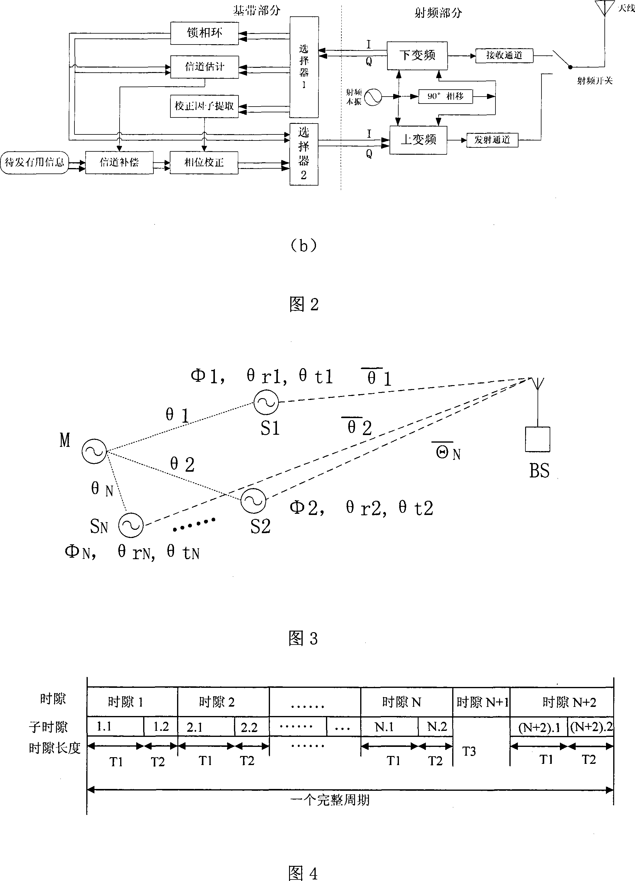
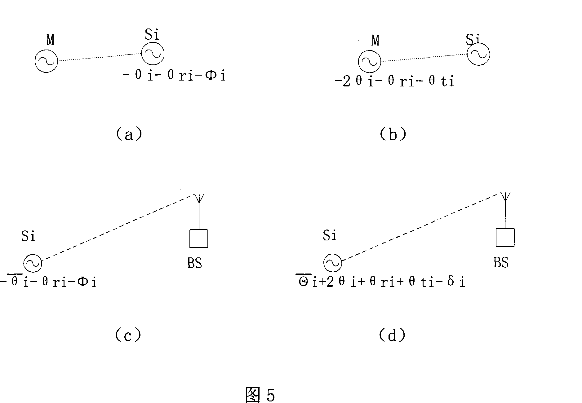
[0028] The present invention will be further described in detail below in conjunction with the accompanying drawings and embodiments.

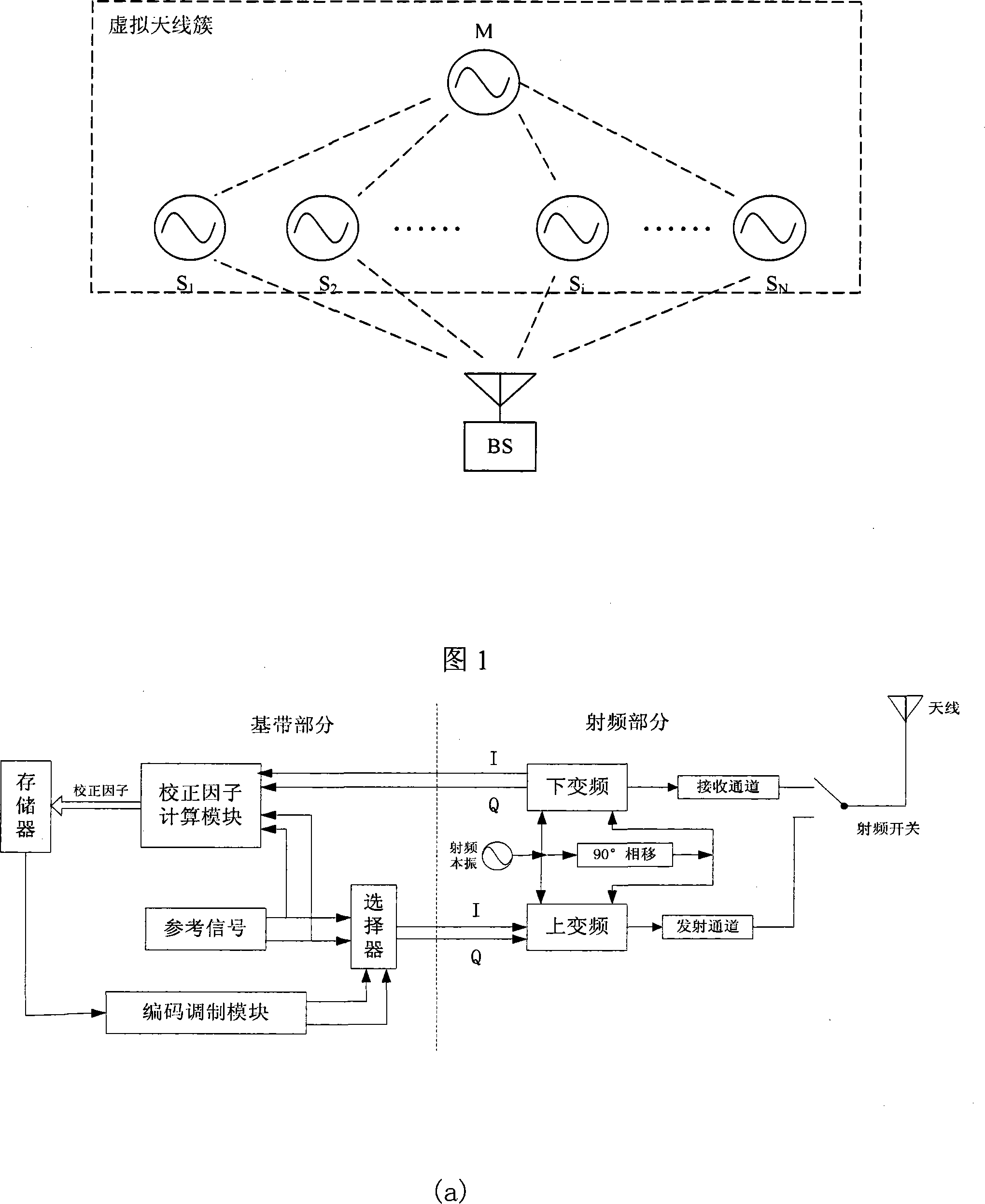
[0029] The implementation manner of the present invention is described by taking a wireless sensor network (Wireless Sensor Network, WSN) application as an example.

[0030] Referring to Fig. 1, the present invention includes a cluster of energy-constrained wireless sensor nodes and a base station BS, which is also called a data collection node in a sensor network. Due to reasons such as random distribution, the communication distance between the sensor node and the base station BS will be relatively long, and the communication range of a single node cannot cover the base station BS. Accurate data collection point to achieve the purpose of long-distance communication. Firstly, a "virtual" antenna array (antenna cluster) is constructed, and a master-slave structure is adopted among the nodes in the cluster, that is, a master node M and N slave...


PUM


Abstract

The invention discloses a method for shaping distributed array aerial beams on the basis of channel calibration, which comprises building a 'virtual' aerial cluster and adopting master-salve structures between each node in the cluster, emitting reference signals to all slave nodes by a master node simultaneously according to preset transceiving time slots, utilizing phase-locked loops to phase-lock received reference signals after each slave node receives the reference signals, then, sending baseband reference signals which are outputted by each phase-locked loop back to the master node in turn through a feedback mode, calculating out corresponding correction factors according to signals which are returned back from each slave node by the master node and storing, broadcasting in a data mode after obtaining the correction factors of each slave node and abstracting each correction factor from data broadcast by each slave node, finally, utilizing obtained correction factor to phase-correct signals which will be sent after estimating and complementing each slave node according to the reference signals which are sent by a receiving key station by each slave node, superimposing in-phase after all signals which are sent by the slave nodes reach the key station, and forming beams on the key station direction.

Description

technical field [0001] The invention relates to a beam forming method of a distributed antenna array, in particular to a beam forming method of a distributed antenna array based on channel correction. Background technique [0002] In a wireless communication system, by weighting the amplitude and phase of the signals received and transmitted by the array channel, the direction and shape of the antenna beam can be controlled to achieve directional transmission and reception for specific users, thereby increasing system capacity and improving signal-to-noise reception Ratio, reduce the transmission power and expand the coverage of the system while ensuring the same communication quality. At the same time, concentrating the transmission energy in a specific direction also improves the security of the communication system. [0003] When the omnidirectional antennas are placed at a certain distance in space, the phase of the radiation field of each antenna is different. This pha...

Claims


Application Information

Patent Timeline
IPC IPC(8): H04B17/00H04L29/08H04B17/12
Inventor 王文杰殷勤业王晨陈刚
Owner XI AN JIAOTONG UNIV
Learn More