
Distributed position estimation for wireless sensor networks

a wireless sensor and distributed position technology, applied in the field of position based services in wireless sensor network, can solve the problems of not all schemes are applicable in a wireless sensor network setting, requires costly special receivers, and is prone to measurement errors in measuring distances, and achieves less environmental protection

Active Publication Date: 2010-10-12
THE HONG KONG UNIV OF SCI & TECH
View PDF22 Cites 56 Cited by
  • Summary
  • Abstract
  • Description
  • Claims
  • Application Information

AI Technical Summary

Benefits of technology

[0006]As the transmission range of each node in a WSN is limited, data forwarding would normally be required to go through multi-hops. It is therefore desirable to lower the number of intermediate nodes, as this implies less communication is required, and thus reducing energy consumption. Optimization of the network topology (in terms of positions of neighboring nodes) provides useful constraints for route correctness and efficiency, and thereby leads to a reduction in the packet loss to the destination nodes, the power consumed for routing, and / or the number of hops to the destination (and hence increase in the throughput).
[0014]Techniques in this category make use of measured angles among nodes to estimate nodal positions via triangulation. Because a triangulation problem can be transformed into a trilateration problem, angle-based techniques enjoy the simplicity in calculation similar to that in distance-based techniques. Further, they are less prone to measurement error caused by signal attenuation, and have better energy conservation and bandwidth utilization as the signal can be sent with a direction. However, this category requires special hardware to measure the angles (e.g. Cricket compasses), which may lead to an increase in cost and energy requirements.
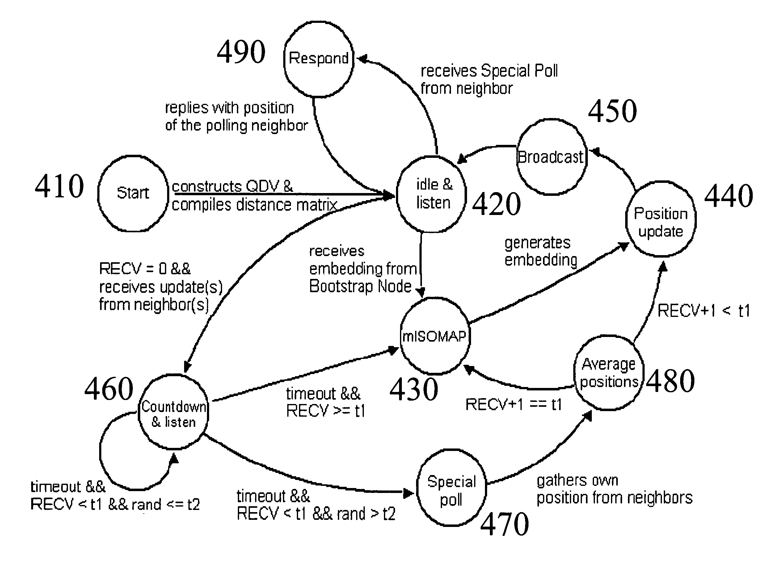
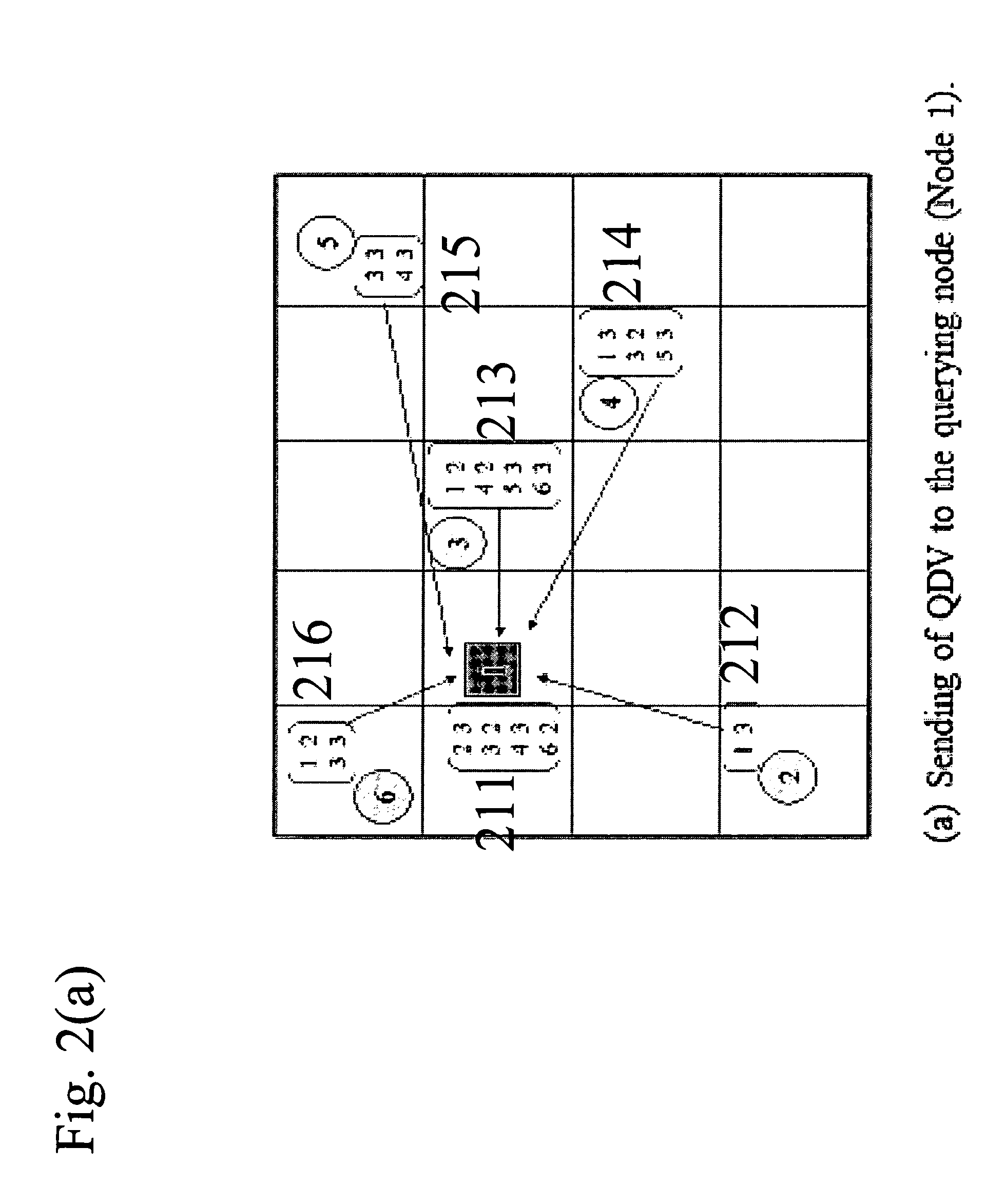
[0017]The present application describes a new distance-based architecture. Each node in this scheme can control its transmission power to discrete values. By varying its transmission power a node can discover its neighbors at discrete distances. Use of a coarse (quantized) distance measurement makes the scheme less environmentally sensitive than architectures which use more precise distance measurements as input. Each node then gathers distance information from immediate neighbors by voluntarily exchanging collected distance information with each other. The accuracy is compensated by each node aggregating distance information from its neighbors. A node then estimates its own position with respect to other nodes by applying Multidimensional Scaling (MDS) on the collected distance information.
[0022]It is robust against measurement noise and channel fading / interference since only imprecise (quantized) information on the distances is needed.
[0024]It is bandwidth efficient as information is exchanged within nodes in proximity only and bandwidth-inefficient global flooding is avoided.

Problems solved by technology

Unlike other wireless networks, WSNs are characterized by many nodes (usually in excess of a hundred) of high density, low computational power and limited transmission range.
Hence, not all schemes are applicable in a wireless sensor network setting.
While it provides a fairly accurate estimation up to meters, it requires costly special receivers and high energy demanding for networks with a large number of nodes, such as sensor networks.
While these techniques usually have the advantages of simple calculation and without special hardware requirements, they are often prone to measurement errors incurred in measuring distances.
Depending on the way distances are measured, the degree of error varies with the changing environment.
However, this category requires special hardware to measure the angles (e.g. Cricket compasses), which may lead to an increase in cost and energy requirements.
While these techniques are less prone to measurement errors in ranges compared with the previous two categories, in most cases, however, a prior knowledge of the map and a careful design of to-be-sensed patterns are necessary, which may not be available or practical in certain wireless sensor networks.

Method used


Image

  • Distributed position estimation for wireless sensor networks
  • Distributed position estimation for wireless sensor networks
  • Distributed position estimation for wireless sensor networks

Examples


Embodiment Construction

[0048]The numerous innovative teachings of the present application will be described with particular reference to the presently preferred embodiment (by way of example, and not of limitation).

A. Location Estimation

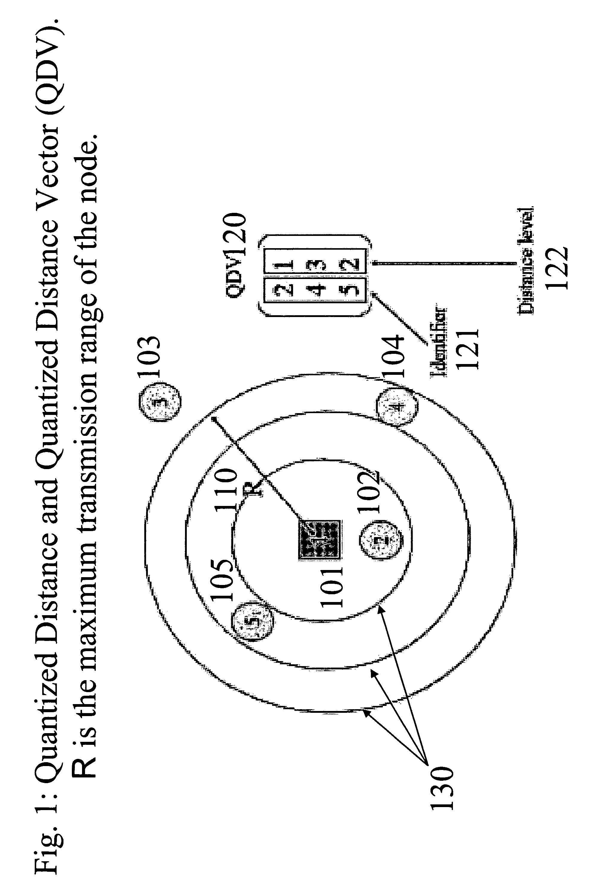
[0049]In the system, every node has a unique identifier (ID) and has a maximum transmission range R. In this embodiment the node is assumed to be able to adjust its power so that it can communicate with its neighbors at discrete distances away. For ease of discussion, it is further assumed that its coverage is represented by concentric circles with a step-wise increase in radius. Again for simplicity of discussion, the nodes here are limited to homogeneous nodes, i.e., they have the same transmission range R and the same levels of quantized distances. Note that this embodiment can easily be extended to handle other non-circle coverage shapes and heterogeneous nodes.

[0050]In FIG. 1 the distance discovery process for the square node with ID 1 is shown 101. FIG. 6 shows an ex...


PUM


Abstract

An effective method of allowing a sensor node to estimate its own position, based only on coarse distances to its neighbors, together with an embedding mathematical tool. This method involves four major steps for each of the nodes: estimating distances to and exchange distance information with nearby nodes; performing position estimation locally; broadcasting the result; and refining its estimation. It also supports nodes joining / leaving the network and nodes with lower power. Further, because useful information for position-based routing is already embedded during the position estimation process, no extra transmission is required for efficient route determination in reporting data to a collecting node.

Description

CROSS REFERENCE TO RELATED APPLICATIONS[0001]This application claims priority from U.S. provisional patent application 60 / 738,062 filed on Nov. 21, 2006, which is hereby incorporated by reference.BACKGROUND AND SUMMARY OF THE INVENTION[0002]The present application relates to nodal position estimation in wireless networks, and more particularly to position based services in wireless sensor networks.[0003]A Wireless Sensor Network (WSN) is a group of sensor nodes performing some sensing tasks jointly through wireless radio interface. Unlike other wireless networks, WSNs are characterized by many nodes (usually in excess of a hundred) of high density, low computational power and limited transmission range. Depending on the application, sensor nodes can be stationary or mobile. A stationary (or low mobility) network discussed here is commonly used for environmental monitoring type of applications, which is one of the major applications of WSNs. These applications include e.g. monitoring...

Claims


Application Information

Patent Timeline
IPC IPC(8): G08B1/08
CPCG01S5/0289H04W40/20H04W64/00H04W48/08Y02B60/50Y02D30/70
Inventor CHAN, GARY SHUENG-HANCHEUNG, VICTORWONG, KIN-FUNGTSANG, IVOR WAI HUNGKWOK, JAMES TIN YAU
Owner THE HONG KONG UNIV OF SCI & TECH
Learn More