Arrangement and method for the generation of extreme ultraviolet radiation by means of an electrically operated gas discharge

an electrically operated gas and gas discharge technology, applied in the direction of optical radiation measurement, instruments, therapy, etc., can solve the problems of insufficient euv projection lithography life of electrodes constructed in these ways, insufficient for the required output specification of an euv source, limited rotation speed of electrodes, etc., to achieve the effect of facilitating the adjustment of layer thickness

Inactive Publication Date: 2010-10-12
USHIO DENKI KK
View PDF8 Cites 3 Cited by
  • Summary
  • Abstract
  • Description
  • Claims
  • Application Information

AI Technical Summary

Benefits of technology

[0011]Therefore, it is the primary object of the invention to facilitate adjustment of the layer thickness and, in particular, to prevent an uncontrolled accumulation of the metal layer to be applied to the rotary electrodes during pauses in the pulse operation for generating radiation when, e.g., liquid flows through these rotary electrodes for efficient cooling. In this connection, the rotating speed of the rotary electrodes can be increased in particular until there is always a freshly coated surface region of the electrodes in the discharge area at repetition frequencies of several kilohertz.
[0018]In order to prevent electrical short-circuiting, it is advantageous when a disk-shaped insulating body which penetrates into the intermediate space between the two electrodes is provided in the electrode area to which the molten metal is to be applied. In this construction, the coating nozzles which are directed to the electrode surfaces of the two electrodes can be guided through the disk-shaped insulating body from opposite sides.
[0019]The arrangement according to the invention can be further developed in a particularly advantageous manner in that the coating nozzle comprises two microstructured plates which lie one on top of the other, and a portion of a first plate is perforated by a hole structure, the second plate being outfitted with a membrane which lies opposite to the hole structure and which is flexible toward the hole structure. A closure element for the hole structure which can be pressed against the hole structure by actuating means acting at the flexible membrane is arranged on the flexible membrane so that the flow of molten metal can be interrupted. Accordingly, a movement away from the hole structure allows the molten metal to resume flowing. The two plates enclose a channel into which the hole structure opens and which is guided out of the first plate as a nozzle outlet.
[0020]The hole structure can also serve as a filter for larger particles in order to prevent clogging of the coating nozzle in that the hole structure has hole diameters that are smaller than the diameter of the nozzle outlet. Further, the coating nozzle can be constructed so as to be heatable by means of a current-carrying resistor which is arranged on the surface of at least one of the plates.
[0024]The inventive application of molten metal is also particularly advantageous because the contact between the rotary electrodes and the discharge circuit can have a particularly low inductance owing to a horizontal arrangement of the two rotary electrodes.
[0029]In a particularly advantageous manner, the electrodes are cooled during coating by a coolant which has an operating temperature below the melting temperature of the material provided for the molten metal. Further, the cooling can be regulated.

Problems solved by technology

Studies of a large number of electrode shapes for gas discharge sources such as, e.g., Z-pinch electrodes, hollow-cathode electrodes or plasma focus electrodes have shown that the life of electrodes constructed in these ways is insufficient for EUV projection lithography.
The solution proposed in WO 2005 / 025280 has the following disadvantages: Because of the immersion process, the rotating speed of the electrodes is limited and is not sufficient for the required output specification of an EUV source.
Owing to insufficient rotating speed, subsequent arrival of unconsumed electrode portions in the discharge area is too slow, which causes instabilities in the plasma generation.
Because of the short dwell period of the electrodes in the molten metal, cooling the electrodes by means of the melt is insufficient for the required high output specifications.
This would result in a heavy, uncontrolled accumulation of the metal layer on the electrodes.
Since this temperature gradient balances out when the additional cooling is switched off, an impermissibly high heating of the coolant can occur so that any gas bubbles that might possibly occur form a thermally insulating layer which prevents efficient cooling.
Further, it is difficult to adjust the layer thickness of the applied material.

Method used


Image

  • Arrangement and method for the generation of extreme ultraviolet radiation by means of an electrically operated gas discharge
  • Arrangement and method for the generation of extreme ultraviolet radiation by means of an electrically operated gas discharge
  • Arrangement and method for the generation of extreme ultraviolet radiation by means of an electrically operated gas discharge

Examples


Embodiment Construction

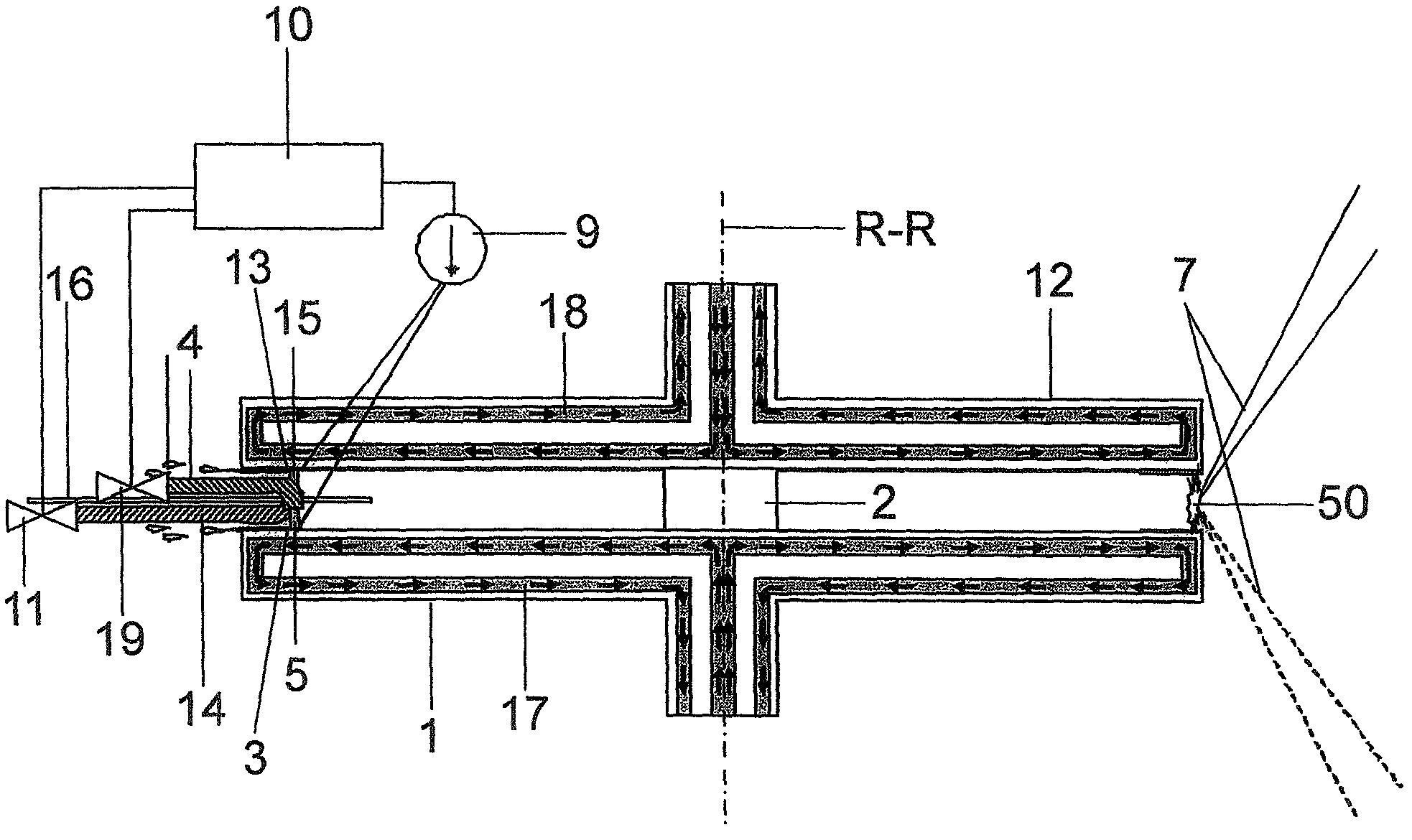
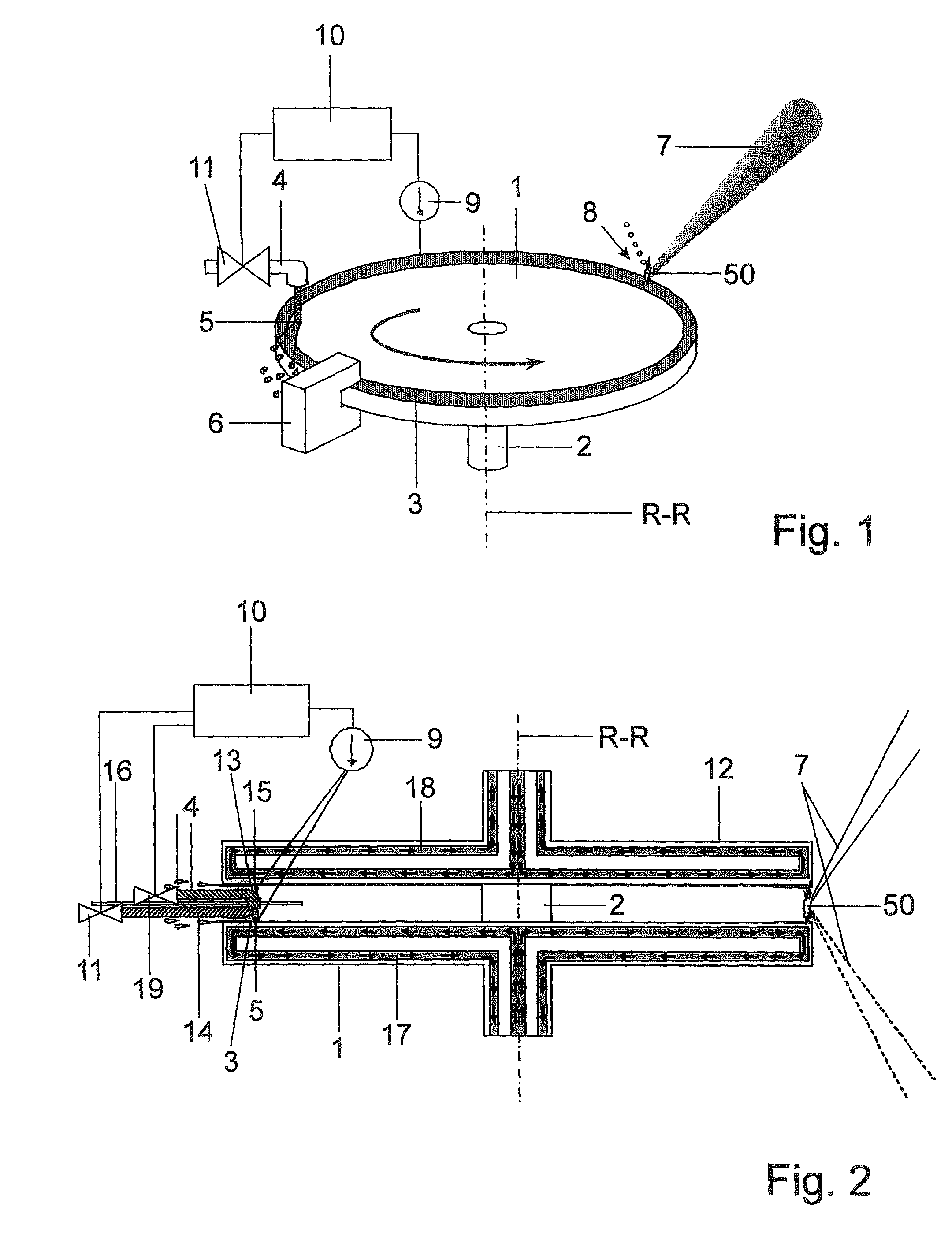
[0041]In FIG. 1, which serves to illustrate the principle of the invention, a disk-shaped electrode 1 is rigidly connected to a rotatable shaft 2 in such a way that the center axis of symmetry of the electrode coincides with the axis of rotation R-R. A circumferential edge track on the electrode surface serves as a receiving area 3 for a molten metal, e.g., tin or a tin alloy, and is formed so as to be wetting for this material. Surfaces for the edge track having a wetting action can be, e.g., copper, chromium, nickel or gold. However, a structural steel, heat-treated molybdenum or other electrically conductive materials are also suitable.

[0042]The rest of the electrode surface, or at least a portion of the electrode surface adjoining the receiving area, should not be wetting for the material to be applied because application of the molten metal to these areas is not wanted. Suitable non-wetting surfaces can comprise, e.g., PTFE, stainless steel, glass, or ceramic.

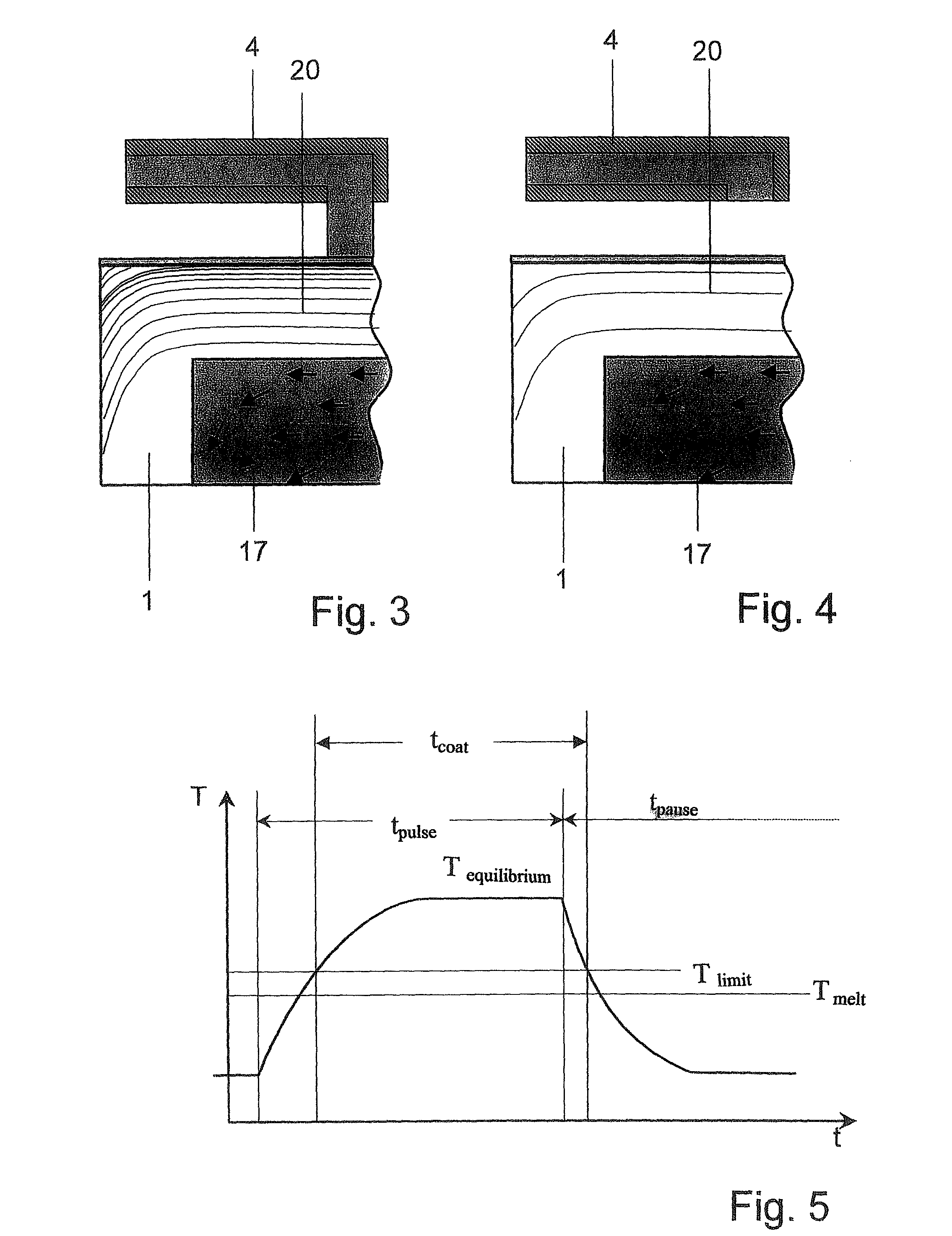
[0043]A coating no...


PUM


Abstract

The object of an arrangement and a method for generating extreme ultraviolet radiation by an electrically operated gas discharge is to improve the adjustment of the layer thickness and, in particular, to prevent an uncontrolled accumulation of the metal layer to be applied to the rotary electrodes during pauses in the pulse operation for generating radiation when, e.g., liquid flows through these rotary electrodes for efficient cooling. In this connection, the rotating speed of the rotary electrodes can be increased in particular until there is always a freshly coated surface region of the electrodes in the discharge area at repetition frequencies of several kilohertz. An edge area to be coated on at least one electrode has at least one receiving area which extends in a closed circumference along the electrode edge on the electrode surface and which is formed so as to be wetting for the molten metal. A coating nozzle for regenerative application of the molten metal is directed to this receiving area and has a shutoff valve connected to a valve regulating device.

Description

CROSS-REFERENCE TO RELATED APPLICATION[0001]This application claims priority of German Application No. 10 2007 004 440.4, filed Jan. 25, 2007, the complete disclosure of which is hereby incorporated by reference.BACKGROUND OF THE INVENTION[0002]a) Field of the Invention[0003]The invention is directed to an arrangement for generating extreme ultraviolet radiation by means of an electrically operated gas discharge, containing a discharge chamber which has a discharge area for a gas discharge for forming a radiation-emitting plasma, a first disk-shaped electrode and a second disk-shaped electrode, at least one of which electrodes is rotatably mounted and has an edge area to be coated by a molten metal, an energy beam source for supplying a pre-ionization beam, and a discharge circuit connected to the electrodes for generating high-voltage pulses.[0004]The invention is further directed to a method for generating extreme ultraviolet radiation by means of an electrically operated gas disc...

Claims


Application Information

Patent Timeline
Patent Type & Authority Patents(United States)
IPC IPC(8): H05B31/26
CPCH05G2/003H05G2/005
Inventor HERGENHAN, GUIDOZIENER, CHRISTIANMOERITZ, MIKE
Owner USHIO DENKI KK
Why Eureka
Try Eureka