
Systems and methods for data transfers between memory cells

a technology of memory cells and data transfers, applied in the field of memory systems, can solve the problems of system operation, data latency in the memory is increasingly becoming a problem, and the use of older technology is rapidly becoming less useful and even obsolete, so as to reduce the latency of data transfers and the additional latency associated with the effect of latency

Active Publication Date: 2010-10-05
TOSHIBA AMERICA ELECTRONICS COMPONENTS
View PDF11 Cites 387 Cited by
  • Summary
  • Abstract
  • Description
  • Claims
  • Application Information

AI Technical Summary

Benefits of technology

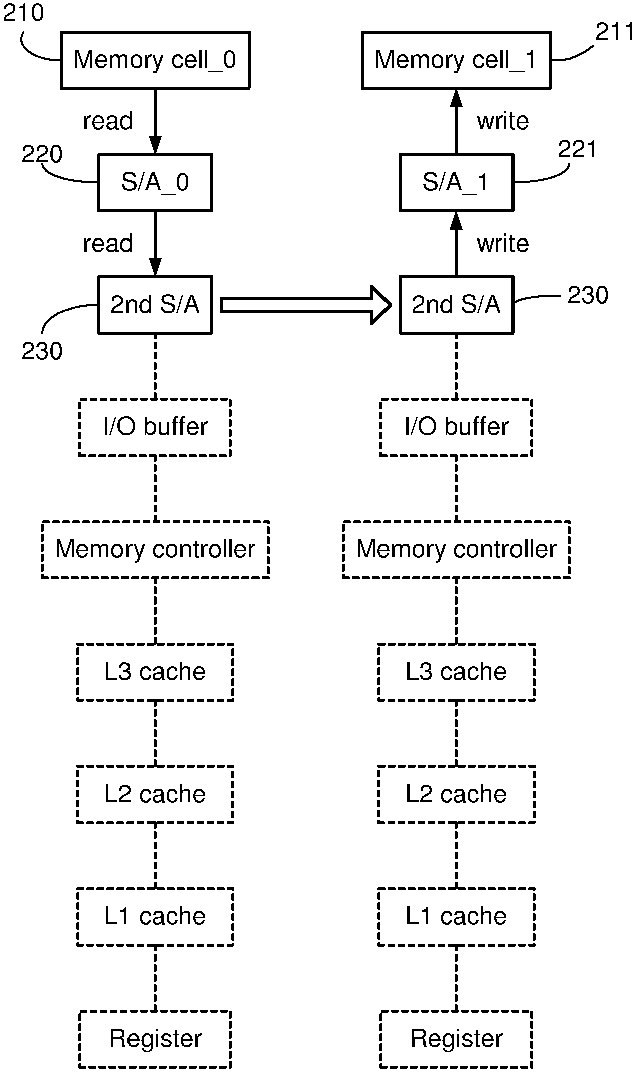
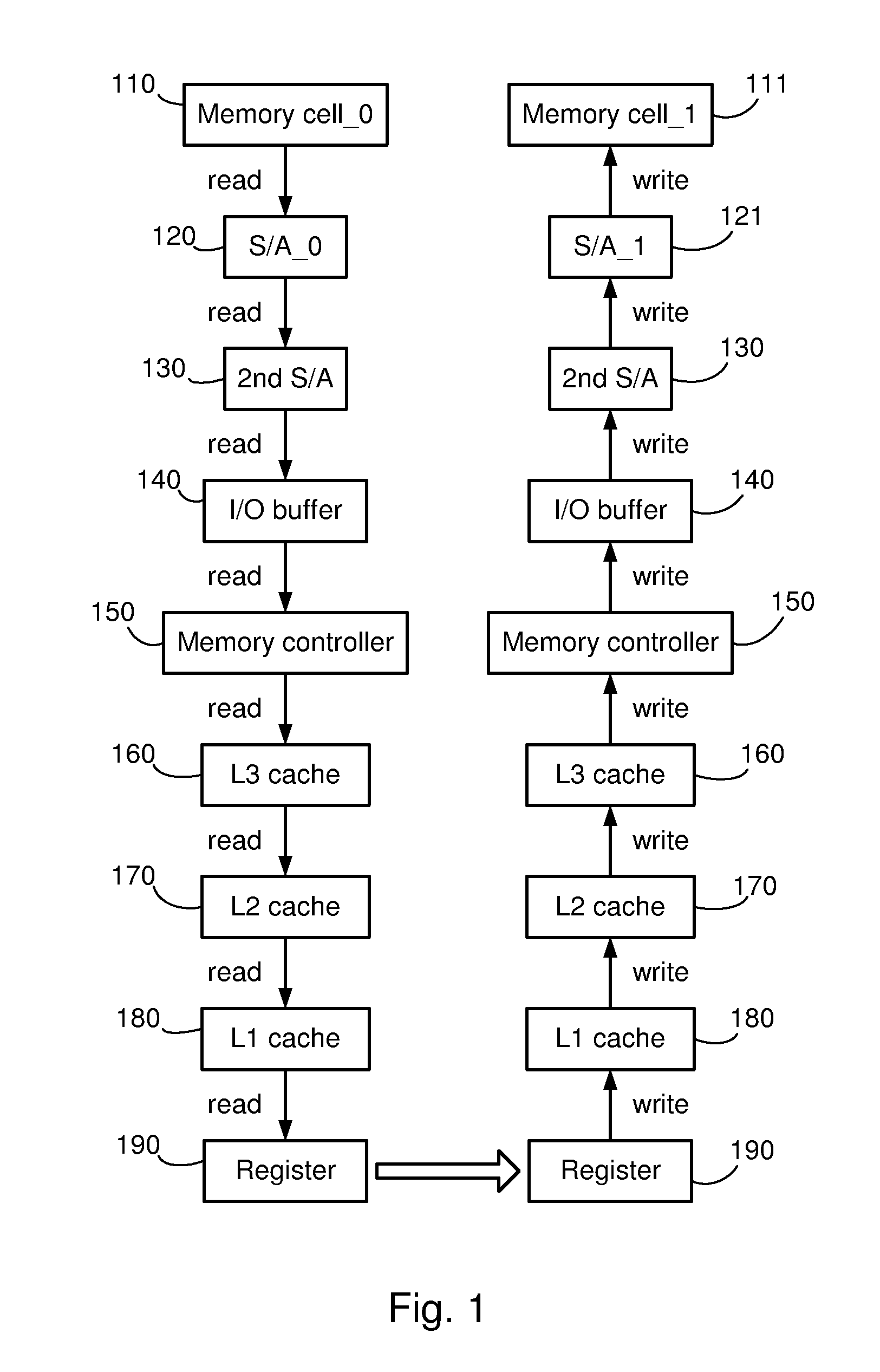
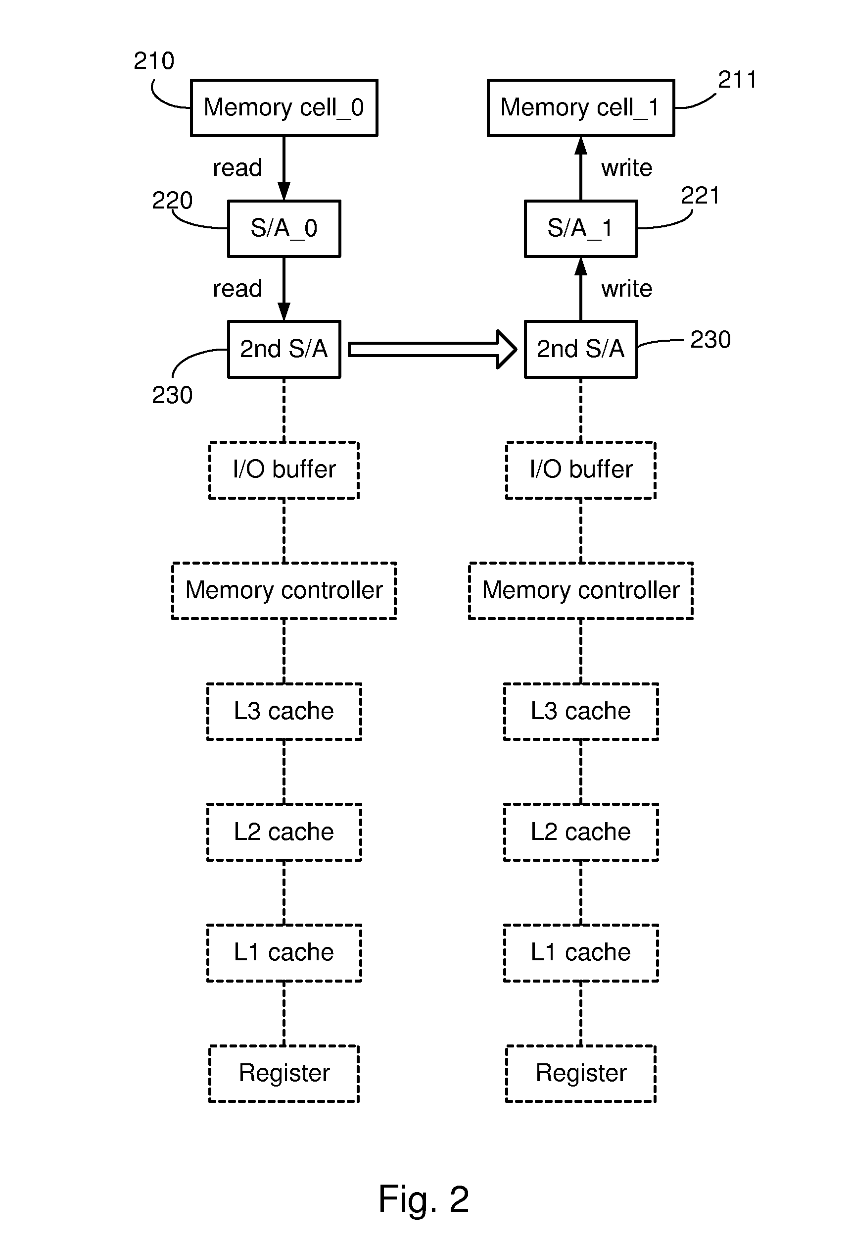
"The invention is about reducing latency in data transfers between memory cells by enabling data to be transferred directly between sense amplifiers in the memory system. This is achieved by using a conventional DRAM memory structure but instead of transferring data from a memory cell through this structure to a processor register, and then back through the memory structure to a second memory cell, the data path is short-circuited through the sense amplifiers that are coupled to the memory cells. This eliminates additional latency associated with the portion of the data path passing through these components. The invention includes systems and methods for reducing latency in data transfers between memory cells by enabling data to be transferred directly between sense amplifiers in the memory system."

Problems solved by technology

As the desire for faster and more powerful computing systems drives the development of new technologies, older technology is rapidly become less useful and even obsolete.
As these processors access these large memories, however, the latency of the data in the memories is increasingly becoming a problem.
While the speed at which the memory systems operate has not decreased, in many instances it has not kept pace with increases in processor speed.
While it may appear that data transfers from one memory location to another should not take any appreciable amount of time, this is not the case.

Method used


Image

  • Systems and methods for data transfers between memory cells
  • Systems and methods for data transfers between memory cells
  • Systems and methods for data transfers between memory cells

Examples


Embodiment Construction

[0027]One or more embodiments of the invention are described below. It should be noted that these and any other embodiments described below are exemplary and are intended to be illustrative of the invention rather than limiting.

[0028]Broadly speaking, the invention includes systems and methods for reducing the latency of data transfers between memory cells by enabling data to be transferred directly between sense amplifiers in the memory system. In one embodiment, a memory system uses a conventional DRAM memory structure, but rather than transferring data from a memory cell through this structure to a processor register, and then back through the memory structure to a second memory cell, the data path is short-circuited through the sense amplifiers that are coupled to the memory cells. By avoiding the routing of the data path through the additional memory structure components (e.g., I / O buffers, memory controllers, cache memories, processor registers,) the additional latency associa...


PUM


Abstract

Systems and methods for reducing the latency of data transfers between memory cells by enabling data to be transferred directly between sense amplifiers in the memory system. In one embodiment, a memory system uses a conventional DRAM memory structure having a pair of first-level sense amplifiers, a second-level sense amplifier and control logic for the sense amplifiers. Each of the sense amplifiers is configured to be selectively coupled to a data line. In a direct data transfer mode, the control logic generates control signals that cause the sense amplifiers to transfer data from a first one of the first-level sense amplifiers (a source sense amplifier) to the second-level sense amplifier, and from there to a second one of the first-level sense amplifiers (a destination sense amplifier.) The structure of these sense amplifiers is conventional, and the operation of the system is enabled by modified control logic.

Description

CROSS-REFERENCE TO RELATED APPLICATIONS[0001]This application claims the benefit of U.S. patent application Ser. No. 11 / 425,438, filed Jun. 21, 2006, which is hereby incorporated by reference as if set forth in its entirety.BACKGROUND[0002]1. Field of the Invention[0003]The invention relates generally to memory systems, and more particularly to systems and methods for reducing the time required to transfer data from one memory cell to another by avoiding the routing of the data through a processor or other memory controller.[0004]2. Related Art[0005]As the desire for faster and more powerful computing systems drives the development of new technologies, older technology is rapidly become less useful and even obsolete. Recent processors operate at faster clock speeds than ever before, and memory systems are capable of providing huge amounts of storage for data. As these processors access these large memories, however, the latency of the data in the memories is increasingly becoming a ...

Claims


Application Information

Patent Timeline
Patent Type & Authority Patents(United States)
IPC IPC(8): G11C7/00
CPCG11C7/065G11C7/08G11C7/1048G11C11/4091G11C11/4096G11C7/18G11C11/4097
Inventor TAKASE, SATORU
Owner TOSHIBA AMERICA ELECTRONICS COMPONENTS
Learn More