Supercharge Your Innovation With Domain-Expert AI Agents!

Image reading apparatus

a technology of image reading and reading device, which is applied in the direction of instruments, television systems, and details of the television system, can solve the problems of large fluctuation of current consumption in the driver circuit, inability to perform highly accurate reading operations, and fluctuation of voltage amplitud

Inactive Publication Date: 2010-09-21
FUJIFILM BUSINESS INNOVATION CORP
View PDF41 Cites 9 Cited by
  • Summary
  • Abstract
  • Description
  • Claims
  • Application Information

AI Technical Summary

Benefits of technology

This configuration stabilizes the output signal levels of the CCD sensor, enabling accurate and consistent image reading operations even with increased pixel counts and higher drive signal frequencies, by minimizing the impact of supply voltage fluctuations on the driver circuits.

Problems solved by technology

As a result, when the vertical transfer period ends and the horizontal transfer starts, a large fluctuation of current consumption occurs in the driver circuit.
The fluctuation of current consumption is accompanied by fluctuations of a supply voltage of the driver circuit, which in turn causes fluctuation of voltage amplitudes and the like of the main clock itself.
As a result, an image signal of normal level cannot be obtained as an output signal of the CCD sensor, with the result that highly accurate reading operations cannot be performed.

Method used


Image

  • Image reading apparatus
  • Image reading apparatus
  • Image reading apparatus

Examples


Embodiment Construction

[0018]Hereinafter, embodiments of the present invention will be described in detail with reference to the accompanying drawings.

[0019]FIG. 1 is a side sectional view showing the outline of the configuration of an image reading apparatus to which the present invention is applied. As shown in FIG. 1, an image reading apparatus of this example includes a document reading section 10, an image processing section 20, and an ADF (Automatic Document Feeder) apparatus 30 functioning as a platen cover as well and not having a circulation function. This image reading apparatus is used as an image reading apparatus of an image processing apparatus having, for example, at least a function of reading document images, such as a scanner, a copier, a facsimile, or a multi-function device having their functions.

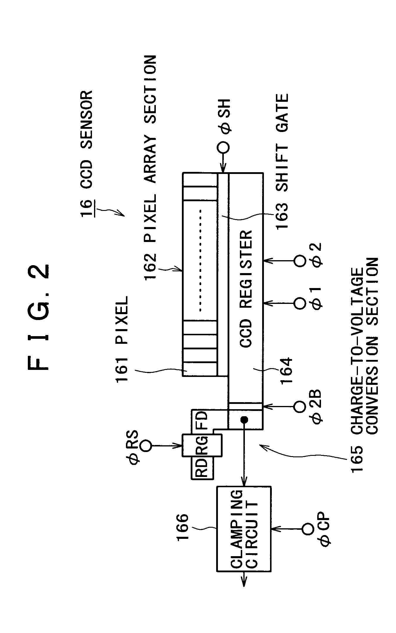
[0020]The document reading section 10 includes a housing 11, a platen glass (document mounting stand) 12, a full rate carriage 13, a half rate carriage 14, a lens 15, and a CCD sensor 16. The ...


PUM


Abstract

An image reading apparatus includes a solid-state image sensor having a pixel array section in which pixels each including a photoelectric transducer are arrayed, a charge transfer register that transfers a signal charge transferred from each of the pixels of the pixel array section, and an output section that converts the signal charge transferred by the charge transfer register into an electrical signal and outputs the electrical signal; a driving unit that drives the charge transfer register according to a first timing signal, and the output section according to a second timing signal; and a power supplying unit that supplies power of different power systems to a circuit portion handling the first timing signal and a circuit portion handling the second timing signal of the driving unit.

Description

BACKGROUND OF THE INVENTION[0001]1. Field of the Invention[0002]The present invention relates to an image reading apparatus, and more particularly to an image reading apparatus of an image processing apparatus having, for example, a function of reading document images, such as a scanner, a copier, a facsimile, or a multi-function device having their functions.[0003]2. Description of the Related Art[0004]In an image reading apparatus of an image processing apparatus having, for example, a function of reading document images, such as a scanner, a copier, a facsimile, or a multi-function device having their functions, for example, a solid-state image sensor represented by a CCD (Charge Coupled Device) type image sensor (hereinafter referred to as a CCD sensor) is used as a unit that optically reads document images.[0005]A CCD sensor used by an image reading apparatus generally has a configuration of a so-called line sensor including: a pixel array section in which a large number of pix...

Claims


Application Information

Patent Timeline
Patent Type & Authority Patents(United States)
IPC IPC(8): H04N1/04H04N1/028H04N1/00H04N1/19H04N1/193H04N23/15
CPCH04N1/00901H04N1/00904H04N1/193H04N3/1581H04N1/00885H04N25/701
Inventor SHIMIZU, MITSUO
Owner FUJIFILM BUSINESS INNOVATION CORP
Features
  • R&D
  • Intellectual Property
  • Life Sciences
  • Materials
  • Tech Scout
  • Unparalleled Data Quality
  • Higher Quality Content
  • 60% Fewer Hallucinations
Learn More