
Wiper arm and cover for a wiper arm

a technology of wiper arm and cover, which is applied in the field of wiper arm, can solve the problems of inadequate and achieve the effect of manufacturing cost effective and adequate stability requirements of the engagemen

Inactive Publication Date: 2010-09-14
ROBERT BOSCH GMBH
View PDF27 Cites 32 Cited by
  • Summary
  • Abstract
  • Description
  • Claims
  • Application Information

AI Technical Summary

Benefits of technology

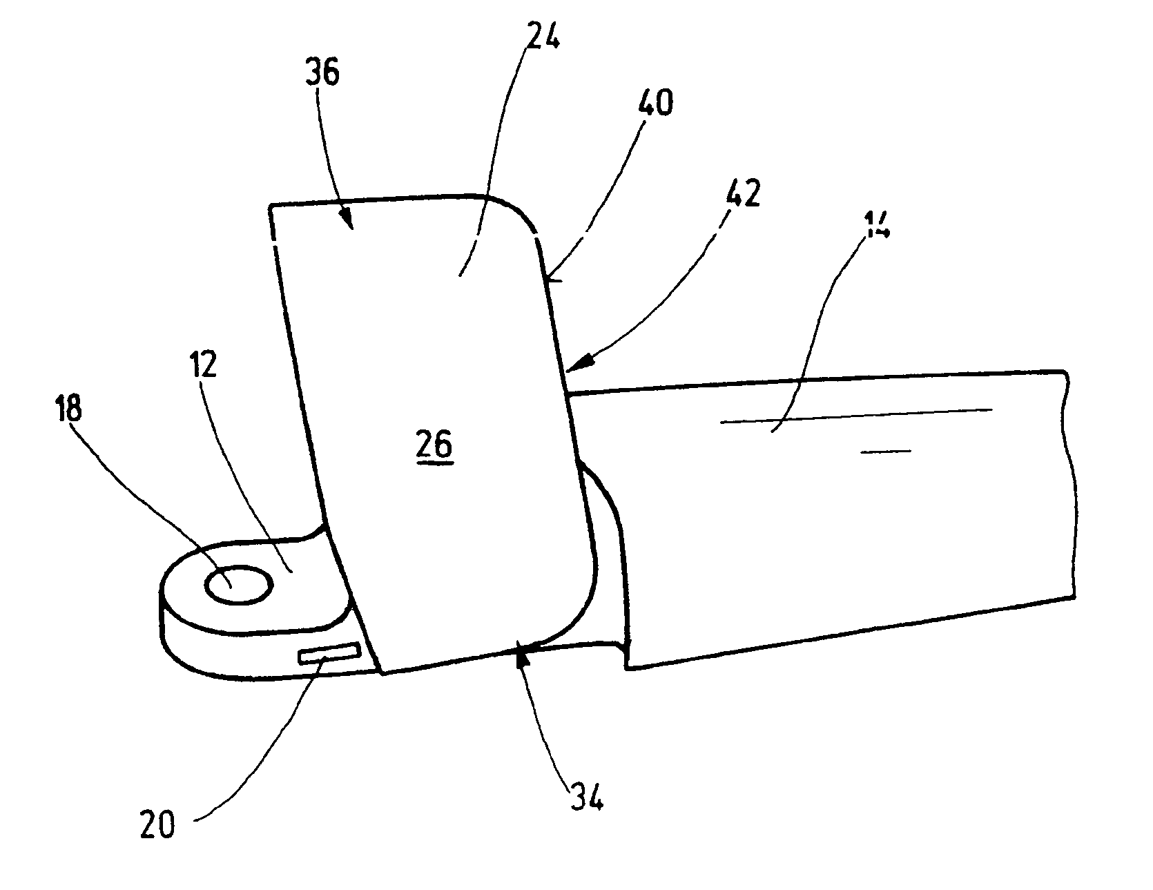
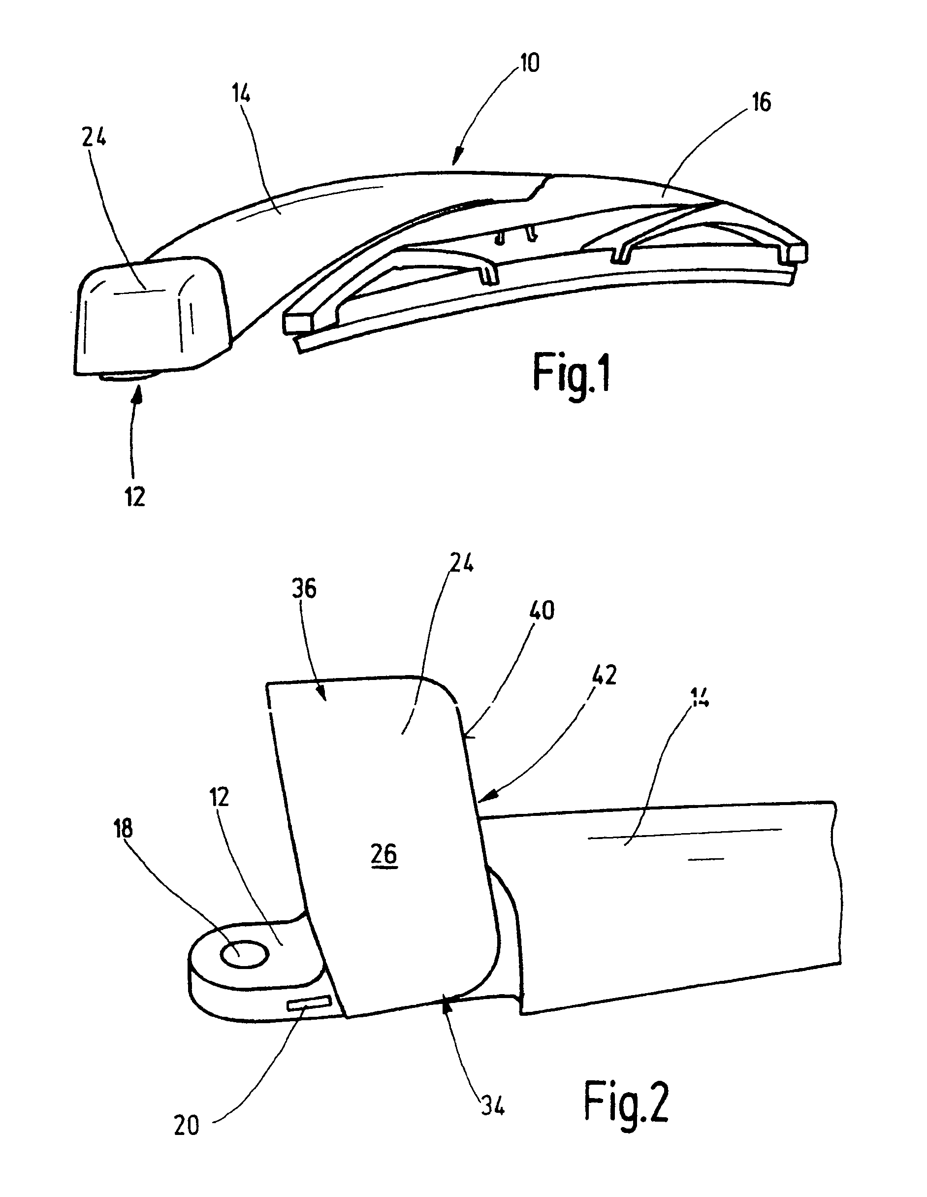
[0003]It is proposed in the case of a wiper arm in accordance with the invention that a cover unit in the tilted position can be engaged with a fixing element of the wiper arm. As a result, the cover unit can be put in a defined position, in which a worker can fasten the wiper arm to a drive shaft through the cover unit without being impeded, preferably by screwing on a front side of the drive shaft. The wiper arm can be mounted ergonomically and securely. Normally, the cover unit is already fastened to the wiper arm, if it is supposed to be mounted to a motor vehicle. The engagement is essentially provided for one-time use during mounting of the wiper arm; as a result, low requirements for stability of the engagement are adequate. The cover unit can therefore be manufactured cost effectively. The engagement between the cover unit and the fixing element can preferably be achieved by a positive engagement or even by locking into place in an undercut.
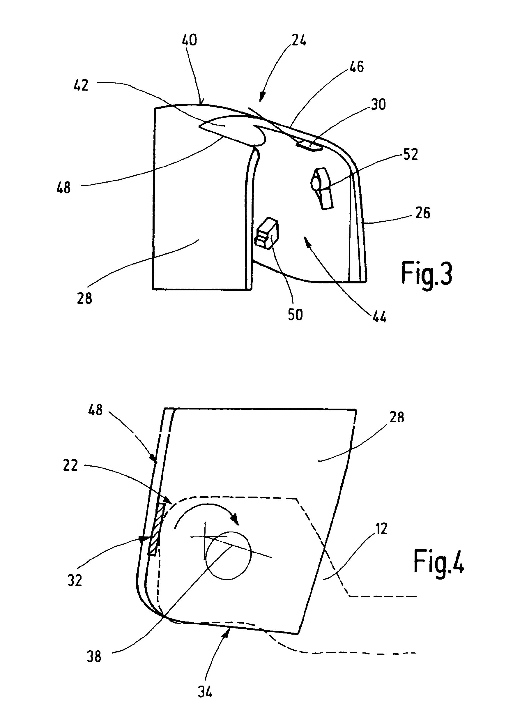
[0004]A particularly simple engagement is possible if the cover unit has an inwardly projecting rib on an inner side of at least one lateral wing. It is beneficial if an inwardly projecting rib is provided on the inner sides of both lateral wings. The lateral wings grip over the fixing element of the wiper arm at least partially.
[0005]If the rib is arranged in such a way that the rib can run at least along a contour of the fixing element when tilting the cover unit, the cover unit can be tilted freely until the rib engages. The cover unit is expediently tilted by approx. 90°. After going beyond a fixing point of the contour, a positive engagement can be produced between the rib and the contour or fixing element. The rib can then be adjacent in a positively engaged manner with the contour. The fixing point can be a formation of the contour, which prevents the rib from gliding over it freely. The rib cannot go beyond the fixing point on its own and therefore cannot tilt back if it has passed this point in the direction of an end position. The rib remains securely in place in the tilted position. A free passage for the assembly of the wiper arm on the drive shaft is guaranteed. Alternatively, an undercut can be provided on the contour into which the cover position hooks when tilting in its end position and which also prevents an undefined tilting back. The cover unit is secured during mounting of the wiper arm and undefined tilting back into its initial position is reliably prevented. Damage to the cover unit from tilting back is prevented.
[0007]Moreover, a cover unit for at least partially covering a wiper arm for a windshield wiper system is proposed, in which an inwardly pointing rib is provided on at least one of its lateral wings, which rib can produce an engagement with the fixing element of the wiper arm. The cover unit is preferably embodied to be capsule-shaped. The cover unit can be manufactured simply and cost effectively. The rib is provided essentially for one-time use during mounting of the wiper arm, a fact that makes the design and manufacture of the cover unit cost effective.
[0008]A reliable connection for long-term use on a wiper arm is possible if the at least one lateral wing has a nose on its inner side for hooking on the fixing element.

Problems solved by technology

The engagement is essentially provided for one-time use during mounting of the wiper arm; as a result, low requirements for stability of the engagement are adequate.

Method used


Image

  • Wiper arm and cover for a wiper arm
  • Wiper arm and cover for a wiper arm
  • Wiper arm and cover for a wiper arm

Examples


Embodiment Construction

[0017]The same reference numbers are used for the same parts in the figures.

[0018]FIG. 1 shows a diagonal view of a wiper arm 10 with a wiper blade unit 16. The wiper arm 10 has a fixing element 12, which is connected in an articulated manner with an articulated arm 14. The articulated arm 14 can include an articulated part and a rigidly attached wiper rod or be embodied as a single piece, preferably made of plastic. The wiper blade unit 16 is suspended on one end of the articulated arm 14. The fixing element 12 is attached on the opposite end. The fixing element 12 has a bearing location on one end, which can be used to connect (e.g., to screw on via a bore hole) the fixing element 12 in a rotationally secured manner to the drive shaft via a fixing means on a drive shaft projecting from a vehicle body. Alternatively, other suitable fastening types can be selected.

[0019]The fixing element 12 is covered at least in the area of the connection to the drive shaft by the tiltably-fixed c...


PUM


Abstract

The invention provides for a wiper arm for a windshield wiper system comprising a fixing element (12) for connection to a drive shaft, whereby a tiltably-fixed cover unit (24) is provided for at least partially releasing the fixing element (12). It is proposed that the cover unit (24) can be engaged with the fixing element (12) in the tilted position. A cover unit for a wiper arm is also proposed.

Description

BACKGROUND OF THE INVENTION[0001]The invention starts with a wiper arm, as well as a cover unit for a wiper arm.[0002]Wiper systems with one or more windshield wipers for motor vehicles are fastened directly or indirectly with their wiper bearings via a mounting plate to the body of the motor vehicle. A motor shaft of a wiper motor directly or indirectly drives, for example via a rod, cranks, which are permanently connected with one end of a drive shaft for each windshield wiper. The drive shaft or the bearing axis is positioned in a wiper bearing. Provided in the bearing housing is at least one radial bearing and one axial bearing on the front sides between the bearing housing and a part that is permanently connected to the drive shaft. The drive shaft projects from the body and moves a wiper arm, which is fastened to its free end and has a wiper blade, over a windshield. As a rule, the wiper arm has a fixing element that is connected in a rotationally secured manner to the drive s...

Claims


Application Information

Patent Timeline
IPC IPC(8): B60S1/34
CPCB60S1/34B60S1/3481B60S1/3484
Inventor VAN DE ROVAART, ROBERT-JAN
Owner ROBERT BOSCH GMBH
Learn More