
Digital radio frequency memory

a digital radio frequency memory and digital technology, applied in pulse manipulation, instruments, pulse techniques, etc., can solve the problem of prohibitive cost of commercially available drfm systems for almost all applications

Inactive Publication Date: 2010-09-07
NAVY U S OF A AS REPRESENTED BY THE SEC OF
View PDF4 Cites 3 Cited by
  • Summary
  • Abstract
  • Description
  • Claims
  • Application Information

AI Technical Summary

Benefits of technology

"The present invention is a digital radio frequency memory that converts analog signals to digital signals using a 14-bit digital-to-analog converter. The digital signal is then down-converted to a lower frequency using a numerically controlled oscillator and mixers. The resulting signal is processed by a band pass filter and a FIFO memory to provide a time delay function. The delayed signals are then up-converted to a higher frequency using another numerically controlled oscillator and a compensating circuit to ensure even distribution of down and up conversions. The resulting signal is then re-converted into an analog signal using a low pass filter to remove unwanted spectral components. The technical effect of this invention is to provide a high-speed, high-resolution digital radio frequency memory that can efficiently process signals in the RF range."

Problems solved by technology

The engineering cost associated with these high speed circuits generally make commercially available DRFM systems cost prohibitive for almost all applications, i.e. in the range of $300,000 to $400,000 per system.

Method used


Image

  • Digital radio frequency memory
  • Digital radio frequency memory
  • Digital radio frequency memory

Examples


Embodiment Construction

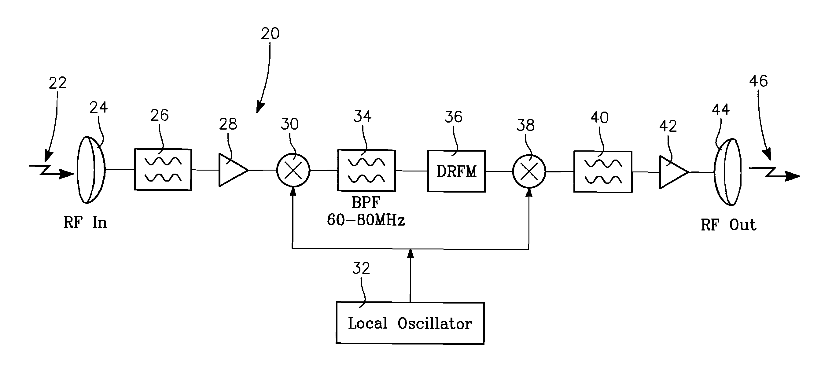
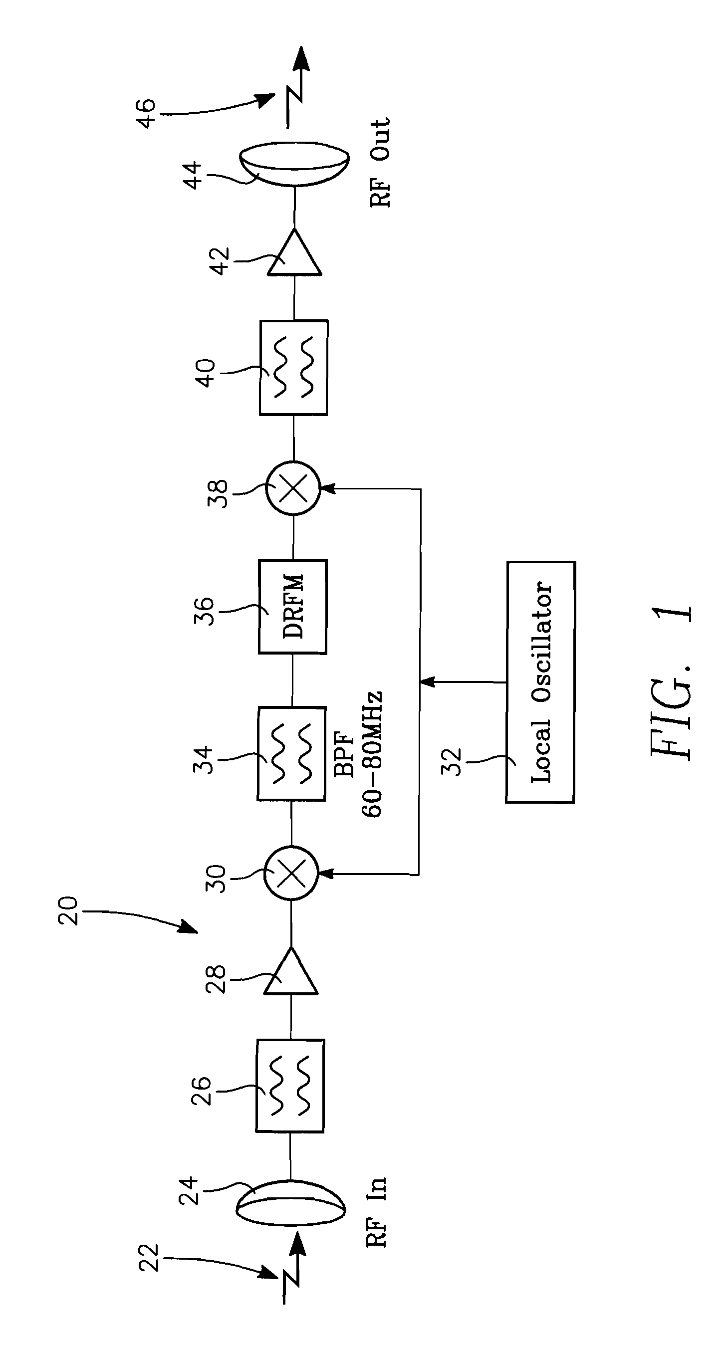
[0014]Referring to FIG. 1, there is shown an electrical schematic diagram of an RF signal processing circuit 20 which receives an incoming RF signal 22. A microwave antenna 24 receives the incoming RF signal 22. An electrical equivalent signal of RF signal 22 is supplied by antenna 24 to a bandpass filter 26. The RF signal 22 has a frequency of 14 GHz.

[0015]Bandpass filter 26 selects a frequency which is compatible with a radar system the digital radio frequency memory is designed to operate with, passing that frequency and rejecting all other frequencies. The bandpass filter 26 has a passband of 13.9 GHz to 14.1 GHz. Connected to the output of filter 26 is an amplifier 28 which amplifies the RF electrical signal.

[0016]Mixer 30 receives the amplified RF electrical signal from amplifier 28, summing the signal with a signal generated by a Local Oscillator 32. The electrical signal output from mixer 30 has a frequency of 70 MHz, which is an IF (Intermediate Frequency) signal. For each ...


PUM


Abstract

A digital radio frequency memory (DFRM) which converts an incoming analog radio frequency signal to a fourteen bit digital signal allowing for digital signal processing and then retransmitted as an analog RF signal. The DFRM provides a time delay for RF signals by storing the signal. The DFRM also changes the signal frequency in the range of plus or minus 100,000 KHz which places a doppler on the signal. The signal phase is changed in a range of 0 to 359 degrees by the DFRM.

Description

[0001]This application is a continuation of U.S. patent application Ser. No. 11 / 801,768, filed Apr. 26, 2007.BACKGROUND OF THE INVENTION[0002]1. Field of the Invention[0003]The present invention relates generally to processing RF signals in a digital format. More particularly, the present invention relates to a low cost digital radio frequency memory which allows an incoming RF signal to be processed digitally and then retransmitted as an analog RF signal.[0004]2. Description of the Prior Art[0005]A Digital Radio Frequency Memory (DFRM) system is designed to digitize an incoming RF signal at a frequency and bandwidth to adequately represent the signal and then reconstruct the RF signal when required for retransmission. Using DFRM provides for digital duplication of the received signal without the signal degradation normally associated with analog memory loops, which continuously cycle energy through a front end amplifier allowing greater range error during jamming and other applicat...

Claims


Application Information

Patent Timeline
Patent Type & Authority Patents(United States)
IPC IPC(8): H03K9/00
CPCH04B1/0021
Inventor DURTSCHI, ROGER DEAN
Owner NAVY U S OF A AS REPRESENTED BY THE SEC OF
Learn More