
Quadrature phase correction circuit

a phase correction circuit and quadrilateral technology, applied in pulse generators, pulse manipulation, pulse techniques, etc., can solve problems such as difficulty in semiconductor device fabrication, and achieve the effect of reducing the number of code counters and reducing the layout siz

Active Publication Date: 2010-09-07
SK HYNIX INC
View PDF2 Cites 9 Cited by
  • Summary
  • Abstract
  • Description
  • Claims
  • Application Information

AI Technical Summary

Benefits of technology

The present invention provides a quadrature phase correction circuit that reduces the size of the circuit by using a single N-bit code counter to generate code values based on detected phase differences. The circuit also includes a storage controller that can share the code counter and control the generation and storage of the code values. Additionally, the circuit includes a duty cycle corrector and a quadrature phase error corrector to make accurate phase corrections. The technical effect of this invention is to reduce the size of the circuit and improve the accuracy of the phase corrections.

Problems solved by technology

However, since the six code counters occupy a large area, there is a difficulty in the fabrication of the semiconductor devices.

Method used


Image

  • Quadrature phase correction circuit
  • Quadrature phase correction circuit
  • Quadrature phase correction circuit

Examples


Embodiment Construction

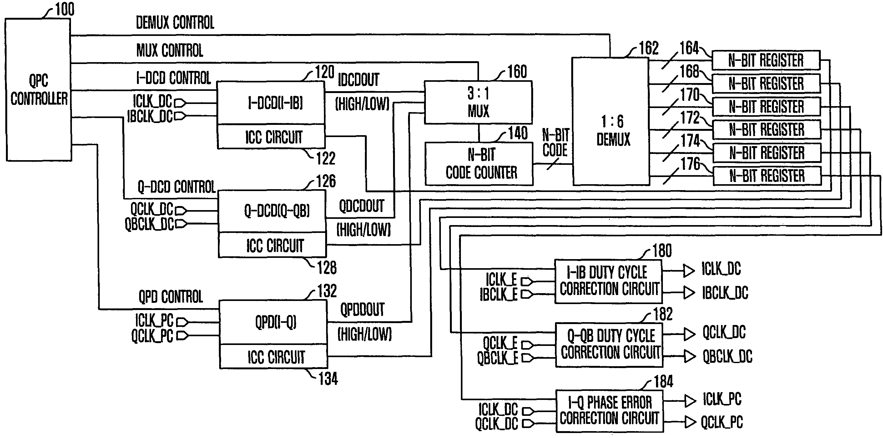
[0045]Hereinafter, a quadrature phase correction circuit in accordance with the present invention will be described in detail with reference to the accompanying drawing.

[0046]FIG. 3 is a block diagram of a quadrature phase correction circuit in accordance with an embodiment of the present invention.

[0047]Referring to FIG. 3, the quadrature phase correction circuit includes a quadrature phase correction control circuit, a phase detection circuit, a duty cycle correction circuit, and a phase error correction circuit. The phase detection circuit detects phases of in-phase (I) and quadrature (Q) clock signals fed back. The duty cycle correction circuit corrects duty cycles of the I-clock signal and the Q-clock signal according to the phase difference detected by the phase detection circuit. The phase error correction circuit corrects the phase error of the I-clock signal and the Q-clock signal whose duty cycles are corrected by the duty cycle correction circuit. In addition, the quadrat...


PUM


Abstract

A quadrature phase correction circuit includes an N-bit code counter configured to generate an N-bit code value according to a detected phase difference when a quadrature phase correction is carried out, N-bit code values are stored according to a plurality of detected phase differences. A controller shares the N-bit code counter, controls the generation of the N-bit code values according to the plurality of detected phase differences, and controls the storing of the N-bit code values in an allocated space of the storage by use of a multiplexer configured to provide the plurality of detected phase differences to the N-bit code counter, and a demultiplexer configured to store the N-bit code values in the allocated space of the storage.

Description

CROSS-REFERENCE TO RELATED APPLICATIONS[0001]The present invention claims priority of Korean patent application number 2008-0033774, filed on Apr. 11, 2008, which is incorporated by reference in its entirety.BACKGROUND OF THE INVENTION[0002]The present invention relates to a quadrature phase correction circuit, and more particularly, to a quadrature phase correction circuit that can reduce a layout size by decreasing the number of code counters.[0003]Synchronous semiconductor devices input and output data in synchronization with a clock signal. Such synchronous semiconductor devices include clock signal generators for generating an internal clock signal synchronized with an external clock signal. One of the clock signal generators is a quadrature phase signal generator to generate a quadrature phase clock signal having a 90-degree phase difference from an external clock.[0004]FIG. 1 is a block diagram of a conventional quadrature phase correction circuit.[0005]Referring to FIG. 1, t...

Claims


Application Information

Patent Timeline
Patent Type & Authority Patents(United States)
IPC IPC(8): H03K5/13
CPCH03L7/0814H03L7/087H03K2005/00286H03K5/00
Inventor YOON, DAE-KUNKWON, DAE-HANSONG, TAEK-SANG
Owner SK HYNIX INC
Learn More