
Full suspension footwear

a full suspension, footwear technology, applied in the direction of bootlegs, uppers, stiffners, etc., can solve the problems of limited travel magnitude that can be employed before incurring excess loss of lateral stability, and none, however, provide practical (quiet, lightweight, robust vs. wear) storage mechanisms, to achieve the effect of maximizing running efficiency and comfor

Active Publication Date: 2010-09-07
KILLION DAVID L +1
View PDF13 Cites 9 Cited by
  • Summary
  • Abstract
  • Description
  • Claims
  • Application Information

AI Technical Summary

Benefits of technology

"The invention is a shoe that simulates the act of running on a hypothetical \"endless\" trampoline, by providing a combination of resilient spring rate and travel capability that matches the weight of the person wearing the shoe. This allows for optimal running efficiency and comfort. The shoe also enables lateral acceleration, with minimal torque on the ankle, and provides cooling for the foot. It also allows for natural toe articulation action and feedback, and provides stability and balance during use. The shoe is designed to be comfortable and running efficient on loose or compressible ground surfaces, and it is lightweight and flexible. It is also designed to minimize wear and tear on the mobile interfaces and clearances over time."

Problems solved by technology

Limitations of these traditional approaches in providing for increasing cushioning with operational safety include 1.) the rising spring rate inherent to elastomer-based compression springs, and 2.) the limited travel magnitude that can be employed before incurring excess loss of lateral stability.
None, however, provide practical (quiet, lightweight, and robust vs. wear) mechanisms for storing and releasing the kinetic energy of a runner's stride while dealing with the increased ankle-turning roll moment due to increased foot elevation, above the ground at impact, that increased cushioning travel entails, and while also providing for direction-of-travel motion control similar to that inherent to the human body's design architecture.

Method used


Image

  • Full suspension footwear
  • Full suspension footwear
  • Full suspension footwear

Examples


first embodiment

[0138]The second principally-preferred extended travel embodiment, LBMA-guided extension member-mounted GCM with triple CFBLs for longitudinally compact resilient urging and pitching mode parallelism control, shares the preferred LBMA extension member concept with the first embodiment described immediately above. Its parallelism control between SSM and GCM is also similar, except that in place of the above dual array CFBL, a more longitudinally compact “Z-like” triple array with angular symmetry of longitudinal links, with respect to extension travel direction, is substituted. The triple array of three conjoined FBLs includes two conjoining links to impose angular orientation control between terminal links. The middle of the three FBLs is preferably nearly twice as long longitudinally as the preferably similar outermost FBLs, such that the terminal links overlap at the center of longitudinal length when the array is vertically most compact. The middle FBL, when located only by the c...

third embodiment

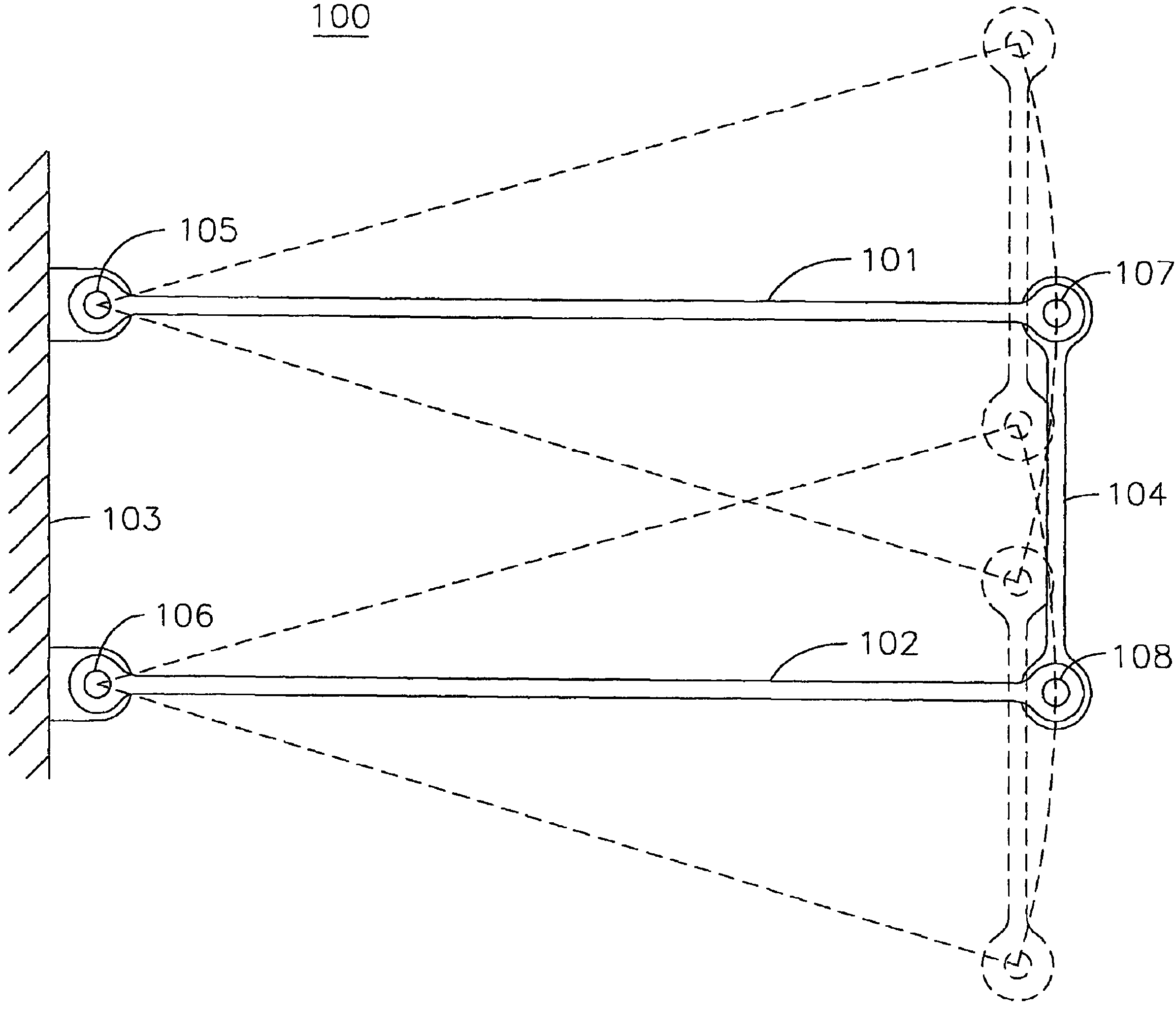
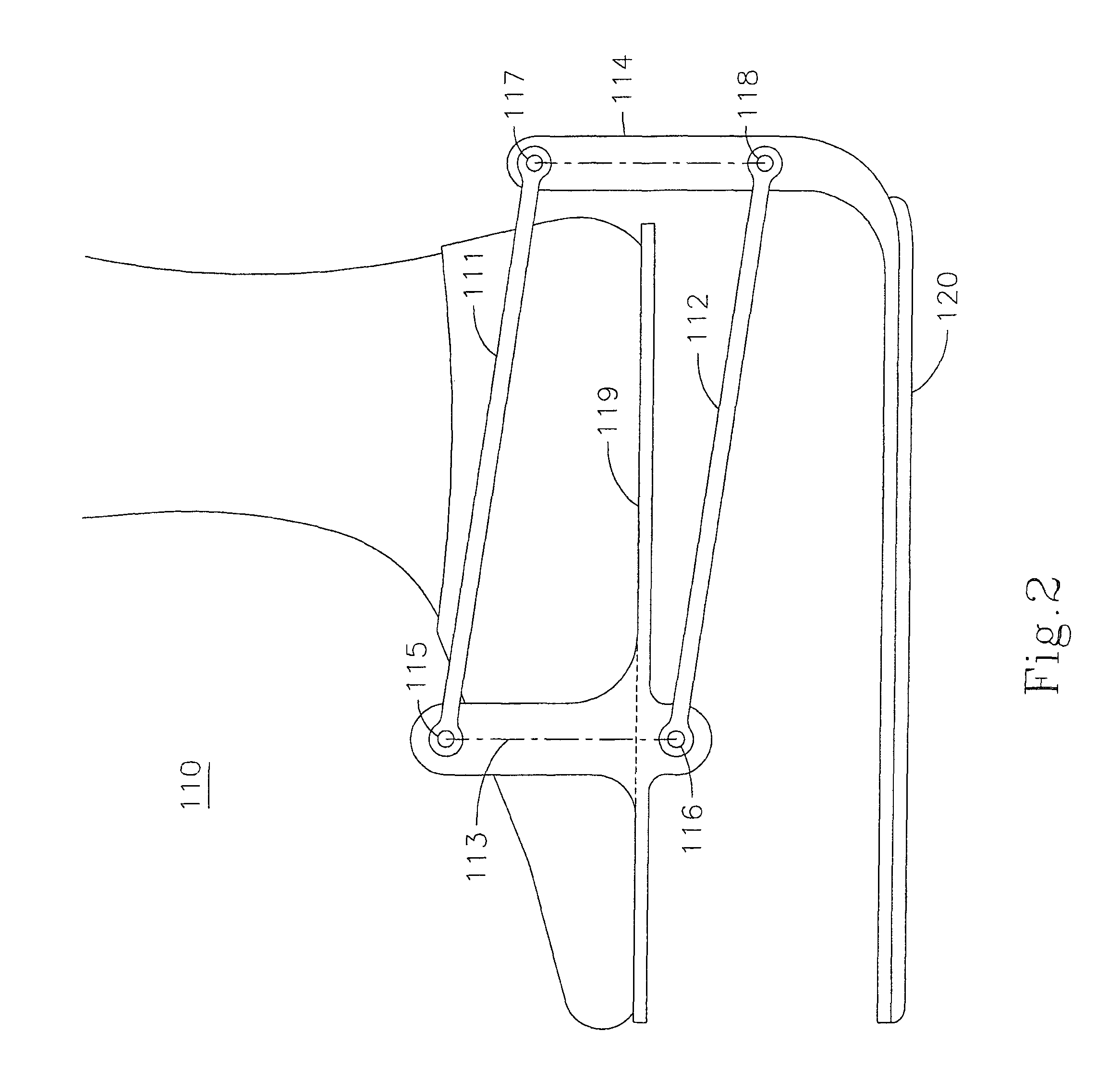
[0208]FIG. 30 is a schematic illustration of moderate travel Full Suspension Footwear motion control apparatus 480, conjoined conjugate four-bar linkages or CCFBLs, which may be substituted for an LBMA by virtue of providing LBMA functionality as discussed earlier. This embodiment is not considered preferred, because of its relatively greater complexity, but it serves to illustrate that the inventive functionality as defined for moderate extension travels may be achieved by a plurality of different structural arrangements that suffice the inventive functionality of normal-to-SSM motion control. In addition to the alternative motion control apparatus, this Figure illustrates inventive Full Suspension Footwear curtaining between GCM and SSM, engineered elasticity or leaf spring bending of GCM for ATPM pivot functionality, and optional, but not preferred, absence of GCM roll mode pivoting for structures other than the prior art Rennex “P-diamond” structure.

[0209]The motion control appa...

fourth embodiment

[0223]FIG. 35 is a schematic illustration of a CR / RPM apparatus, the last of four preferred embodiments for the provision of inventive extended travel motion control, an LBMA-guided extension member-mounted GCM with CR / RPM motion transfer for resilient urging and pitching mode parallelism control: LBMA control of extension member motion is substantially the same as detailed in FIGS. 31-33 for the first two of four preferred embodiments. This fourth embodiment is preferred despite its greater packaging space claim, for its best-in-class linearity of spring rate, and its ability to potentially accommodate high magnitudes of extension travel, advantages that potentially offer the highest performance in terms of airtime and ambulatory travel rates.

[0224]As in FIGS. 31-33, an SBM 621 is fixedly associated with a user's lower leg by a snugging strap 622 and an SSM 625 with a TAPA bearing 623 that locates the SBM 621's lower end, while a transverse axis pivot bearing 629 mounts the GCM 626...


PUM


Abstract

A method and apparatus for enhancing the ability of a human to run and jump with comfort comparable to running barefoot on a trampoline and with control comparable to that of the unaided human form, yet with freedom from ankle-turning roll moments associated with substantial ground contact member (GCM) extension downwardly away from the sole of the foot, including a resiliently urged GCM constrained to two degrees of freedom: translation away from the sole of the user's foot and rotation about a longitudinal axis at ground level. The apparatus relates flexure of a GCM toe pressure member to comparable flexure of user's toes at the metatarsal joints. The apparatus also incorporates lower leg to ankle pivot bracing, and extends the GCM in downward direction parallel to the lower leg while mimicking user ankle articulation with parallelism-maintaining rotation about a downwardly resiliently urged transverse pivot axis similar to the user's own ankle joint for extended travel.

Description

CROSS REFERENCE TO RELATED APPLICATIONS[0001]This application claims priority from U.S. Provisional Patent Application Ser. No. 60 / 577,632, filed Jun. 7, 2004, and entitled “Springy Sport Shoes” and U.S. Provisional Patent Application Ser. No. 60 / 655,925, filed Feb. 24, 2005, and also entitled “Springy Sport Shoes”.TECHNICAL FIELD[0002]The present invention relates to the fields of sporting goods for athletic use, health and fitness equipment, physical rehabilitation, running, jogging, shock absorbing footwear, and the extension of ambulatory exercise benefits to persons with skeletal and / or joint infirmities that currently inhibit such activities because of the impact loadings therein comprised.BACKGROUND OF THE INVENTION[0003]The health benefits of running, jogging and walking are widely known and have been well documented. An entire industry of sporting footwear, running apparel, and related periodical publications dedicated to enhancing these forms of exercise, has arisen in rec...

Claims


Application Information

Patent Timeline
Patent Type & Authority Patents(United States)
IPC IPC(8): A43B3/10A63B25/00
CPCA43B7/38A43B13/183A43B13/184A63B25/10A63C17/0046A63C17/065
Inventor KILLION, DAVID L.KILLION, JESSE
Owner KILLION DAVID L
Learn More