Ophthalmologic examination apparatus
a technology of ophthalmologic examination and apparatus, which is applied in the field of ophthalmologic examination apparatus, can solve the problems of complex optical system of the apparatus that performs a variety of ophthalmologic examinations, cannot be used in medical science, diagnostics, ophthalmoscopes,
- Summary
- Abstract
- Description
- Claims
- Application Information
AI Technical Summary
Benefits of technology
Problems solved by technology
Method used
Image
Examples
first embodiment
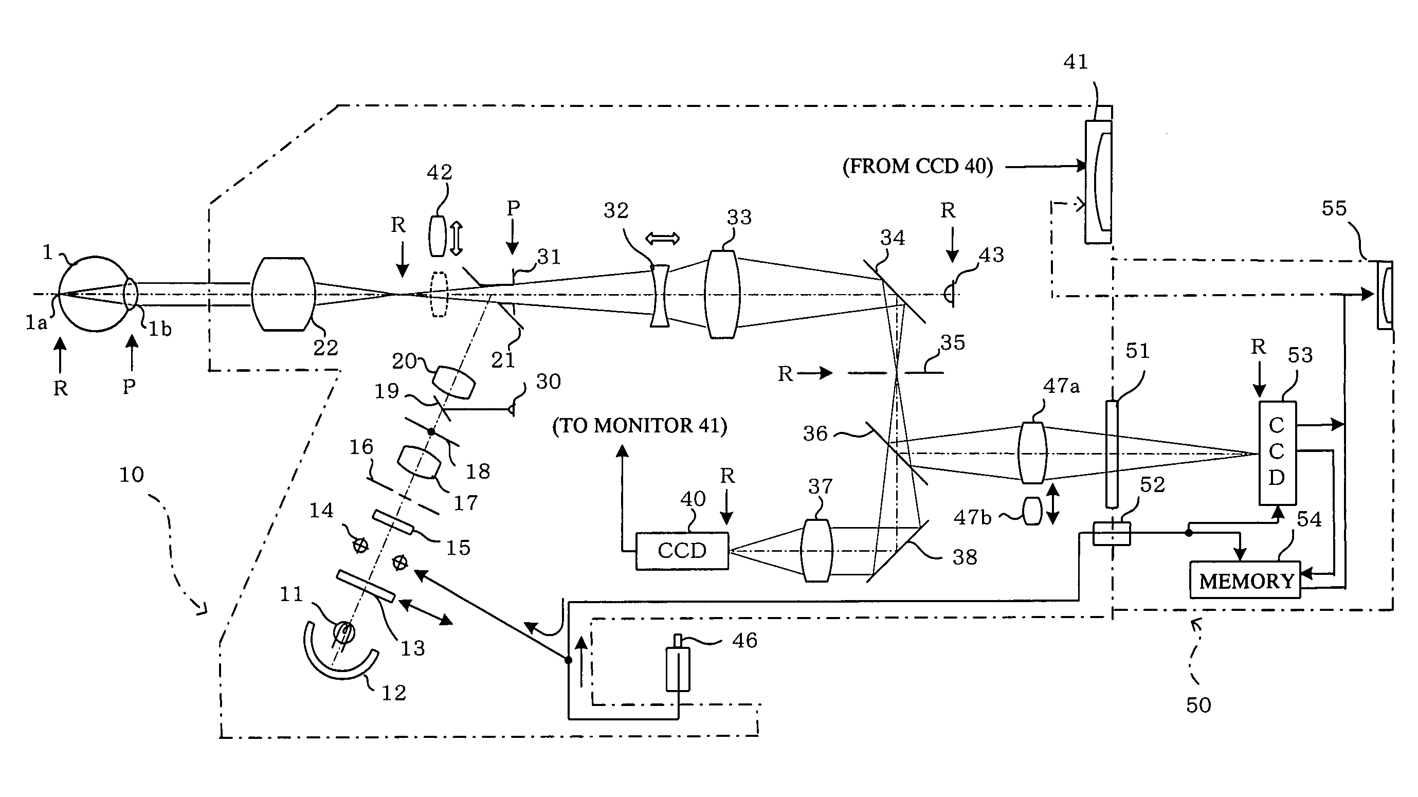
[0020]FIG. 1 shows the present invention in which the ophthalmologic examination apparatus is configured as a non-mydriatic fundus camera.
[0021]In the ophthalmologic examination apparatus shown in FIG. 1, an illuminating optical system for illuminating an eye fundus and an imaging optical system for imaging the illuminated eye fundus are provided to a main unit 10 of the apparatus. In the illuminating optical system, light emitted from a halogen lamp or another light source 11 together with light reflected by a concave mirror 12 forms into infrared light via a visible-cutting / infrared-transmitting filter 13, passes through a stroboscope 14, diffuses on a diffusion plate 15, and illuminates a ring slit 16 disposed at a position conjugate with an anterior ocular segment (pupil) 1b of an eye 1 to be examined. Illuminating light from the ring slit 16 passes through a lens 17, a black spot plate 18 for eliminating the reflection of an objective lens 22, a half mirror 19 and a relay lens ...
second embodiment
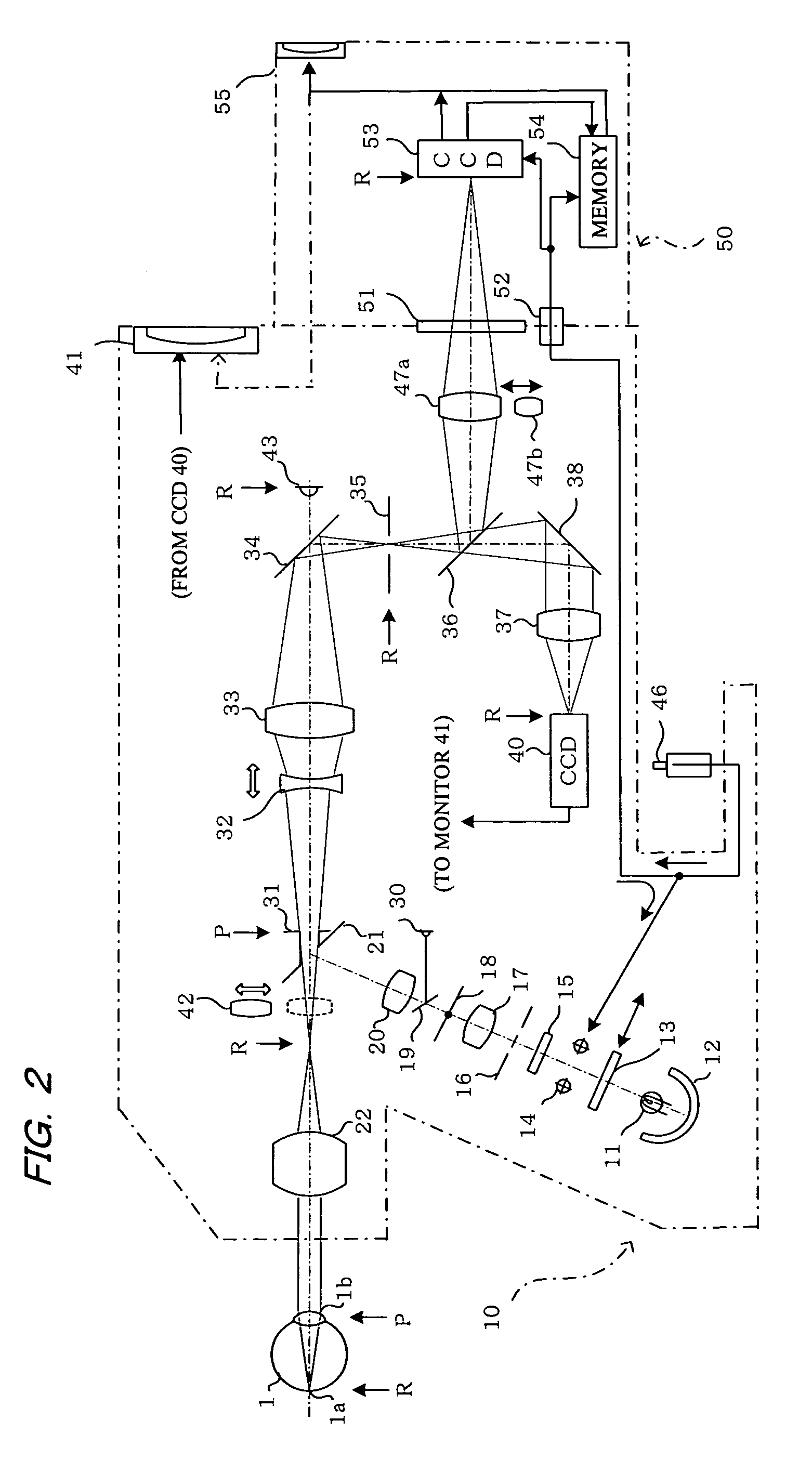
[0034]In the second embodiment, the monitor 55 can be used in place of the monitor 41 of the main unit 10. Alternatively, a monitor can be provided to the imaging device 53 or a monitor can be provided to the exterior of the attachment unit 50. When the monitor 41 is used, the signals from the imaging device 53 and the memory 54 are directed to the monitor 41, as indicated by the dashed line.
[0035]The visible-cutting / infrared-transmitting filter 13 is inserted into or retracted from the optical path in accordance with mydriatic and non-mydriatic modes. The display of the images from the imaging devices 40 and 53 in both the modes is therefore automatically switched in accordance with the insertion and retract of the filter 13.
[0036]In the mydriatic mode, an infrared-cutting / visible-transmitting filter may be inserted into the optical path in place of the filter 13 in order to protect the eye to be examined.
third embodiment
[0037]FIG. 3 shows a third embodiment in which the ophthalmologic examination apparatus is used as a mydriatic and non-mydriatic fundus cameras in the same manner as in FIG. 2. In FIG. 3, the same numeric symbols are applied to parts having functions that are the same as or similar to those of FIGS. 1 and 2, and detailed descriptions thereof have accordingly been omitted. An appearance of this embodiment is shown in FIG. 7.
[0038]In this embodiment, an ocular function is provided to the attachment unit 50, and a return mirror 60 is disposed in the optical path between the mount 51 and the imaging device 53. When the return mirror 60 is in the indicated position, the image of the eye fundus reflected by the return mirror 60 is guided to an ocular lens 63 via a prism 61 and a lens 62, and the image of the eye fundus can be observed via the ocular lens 63. In this instance, a cap (light shielding means) 67 is mounted on a viewing hole 64 of an eyepiece in order to prevent stray light fr...
PUM
 Abstract
Description
Claims
Application Information
 - R&D
- Intellectual Property
- Life Sciences
- Materials
- Tech Scout
- Unparalleled Data Quality
- Higher Quality Content
- 60% Fewer Hallucinations
Browse by: Latest US Patents, China's latest patents, Technical Efficacy Thesaurus, Application Domain, Technology Topic, Popular Technical Reports.
© 2025 PatSnap. All rights reserved.Legal|Privacy policy|Modern Slavery Act Transparency Statement|Sitemap|About US| Contact US: help@patsnap.com


