
Combinatorial synthesis of inorganic or composite materials

Inactive Publication Date: 2010-08-03
RGT UNIV OF CALIFORNIA +1
View PDF36 Cites 19 Cited by
  • Summary
  • Abstract
  • Description
  • Claims
  • Application Information

AI Technical Summary

Benefits of technology

[0015]In yet another embodiment of the present invention, a method is provided for forming at least two different arrays of materials by delivering substantially the same reaction components at substantially identical concentrations to reaction regions on both first and second substrates and, thereafter, subjecting the components on the first substrate to a first set of reaction conditions and the components on the second substrate to a second set of reaction conditions. Using this method, the effects of the various reaction parameters can be studied on many materials simultaneously and, in turn, such reaction parameters can be optimized. Reaction parameters which can be varied include, for example, reactant amounts, reactant solvents, reaction temperatures, reaction times, the pressures at which the reactions are carried out, the atmospheres in which the reactions are conducted, the rates at which the reactions are quenched, the order in which the reactants are deposited, etc.
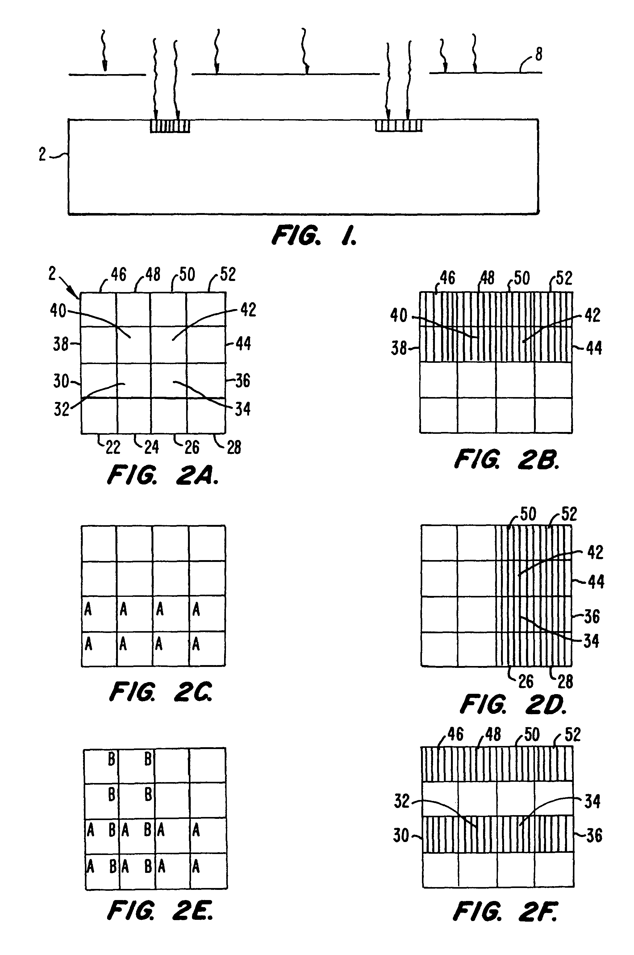
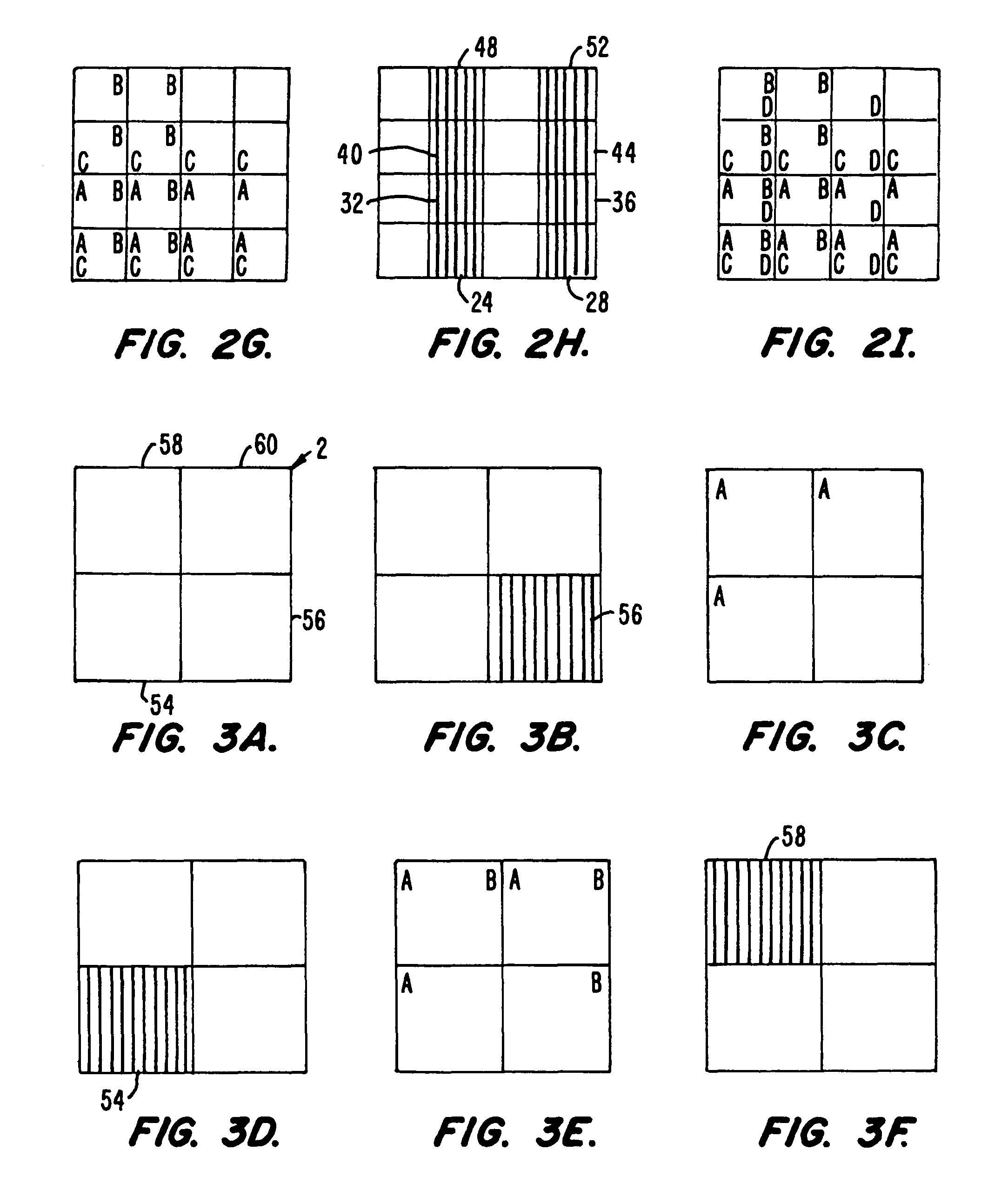
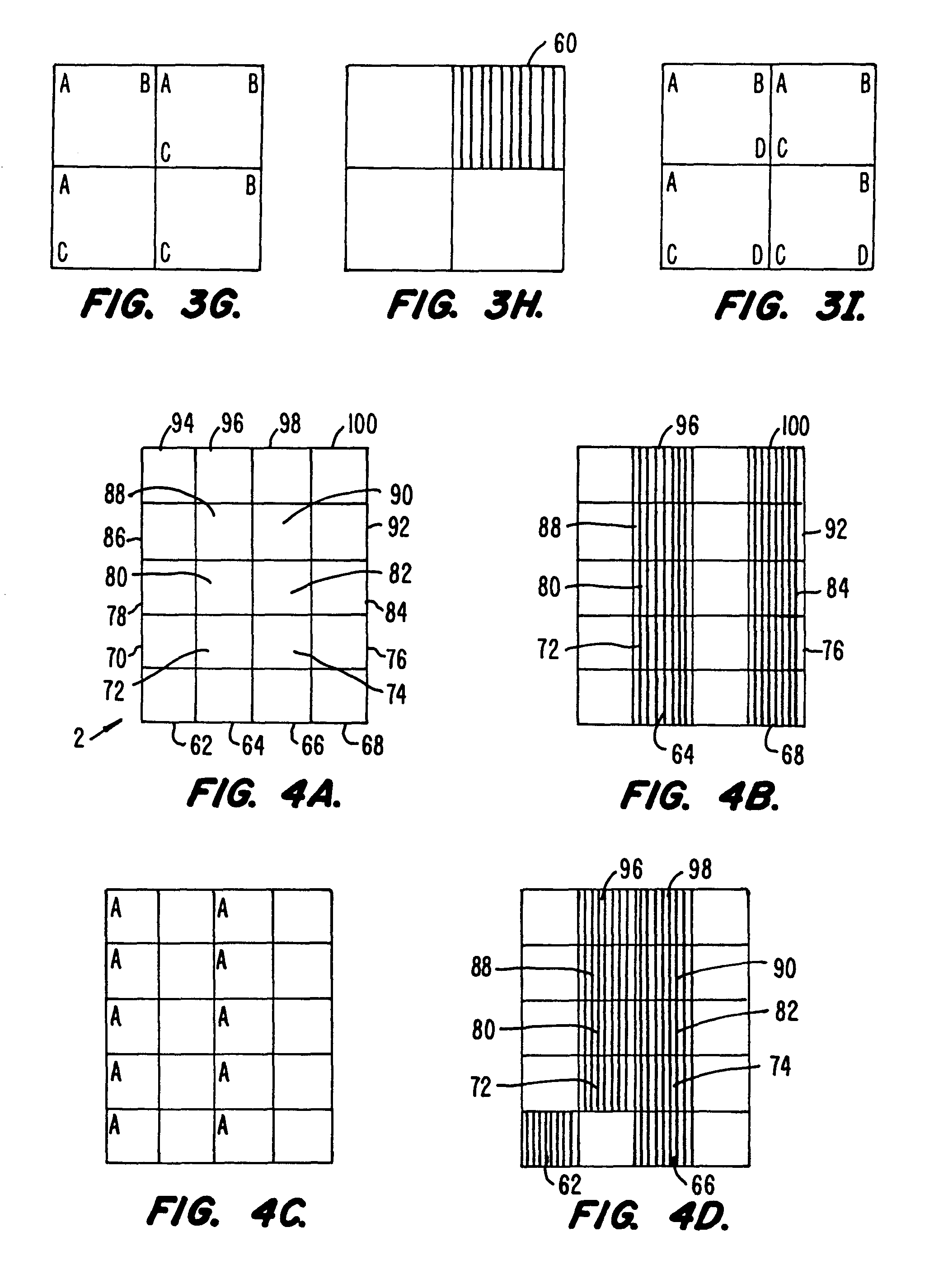
[0016]In the delivery systems of the present invention, a small, precisely metered amount of each component is delivered into each predefined region. This may be accomplished using a variety of delivery techniques, either alone or in combination with a variety of masking techniques. For example, thin-film deposition techniques in combination with physical masking or photolithographic techniques can be used to deliver various components to selected regions on the substrate. Components can be delivered as amorphous films, epitaxial films, or lattice and superlattice structures. Moreover, using such techniques, components can be delivered to each site in a uniform distribution, or in a gradient of stoichiometries. Alternatively, the various components can be deposited into the predefined regions of interest from a dispenser in the form of droplets or powder. Suitable dispensers include, for example, micropipettes, mechanisms adapted from ink-jet printing technology and electrophoretic pumps.
[0017]Once the components of interest have been delivered to predefined regions on the substrate, they can be reacted using a number of different synthetic routes to form an array of materials. The components can be reacted using, for example, solution based synthesis techniques, photochemical techniques, polymerization techniques, template directed synthesis techniques, epitaxial growth techniques, by the sol-gel process, by

Problems solved by technology

Unfortunately, even though the chemistry of extended solids has been extensively explored, few general principles have emerged that allow one to predict with certainty the composition, structure and reaction pathways for the synthesis of such solid state compounds.
Moreover, it is difficult to predict a priori the physical properties a particular three dimensional structure will possess.
These solid phase synthesis techniques, which involve the sequential coupling of building blocks (e.g., amino acids) to form the compounds of interest, cannot readily be used to prepare many inorganic and organic compounds.

Method used


Image

  • Combinatorial synthesis of inorganic or composite materials
  • Combinatorial synthesis of inorganic or composite materials
  • Combinatorial synthesis of inorganic or composite materials

Examples


example 1

[0230]In this embodiment, a first component of first and second materials is delivered to predefined regions on a substrate, then a second component of the first and second materials is delivered to the predefined region on the substrate, and so on for other components (e.g., third, fourth, firth, etc. components) and / or other materials (e.g., third, fourth, fifth, etc. materials). The resulting array of materials, each at a discrete and known locations of the substrate, comprises layers, blends, mixtures or combinations thereof.

example 2

[0231]In another embodiment, the array is formed as in Example 1, but the resulting materials are formed immediately on the substrate as the components contact each other on the substrate.

example 3

[0232]In another embodiment, the array is formed as in Example 1, but after the various components are delivered to the substrate, a processing step is carried out and causes the components to interact to form layers, blends, mixtures, or combinations thereof or, in addition, materials resulting from a reaction between components.


PUM

PropertyMeasurementUnit
Temperatureaaaaaaaaaa

Abstract

Methods and apparatus for the preparation and use of a substrate having an array of diverse materials in predefined regions thereon. A substrate having an array of diverse materials thereon is generally prepared by delivering components of materials to predefined regions on a substrate, and simultaneously reacting the components to form at least two materials or, alternatively, allowing the components to interact to form at least two different materials. Materials which can be prepared using the methods and apparatus of the present invention include, for example, covalent network solids, ionic solids and molecular solids. More particularly, materials which can be prepared using the methods and apparatus of the present invention include, for example, inorganic materials, intermetallic materials, metal alloys, ceramic materials, organic materials, organometallic materials, nonbiological organic polymers, composite materials (e.g., inorganic composites, organic composites, or combinations thereof), etc. Once prepared, these materials can be screened for useful properties including, for example, electrical, thermal, mechanical, morphological, optical, magnetic, chemical, or other properties. Thus, the present invention provides methods for the parallel synthesis and analysis of novel materials having useful properties.

Description

[0001]This application is a continuation-in-part of U.S. patent application Ser. No. 08 / 327,513, filed Oct. 18, 1994 and now issued as U.S. Pat. No. 5,985,356. This application is also a continuation-in-part of U.S. patent application Ser. No. 08 / 483,043, filed May 8, 1995 and now issued as U.S. Pat. No. 5,776,359, which itself is a continuation-in-part of U.S. Ser. No. 08 / 327,513, filed Oct. 18, 1994 and now issued as U.S. Pat. No. 5,985,356. This application is also a continuation-in-part of PCT Application No. US 95 / 13278 filed Oct. 18, 1995 and now published as WO 96 / 11878, which itself claims priority to U.S. Ser. No. 08 / 327,513, filed Oct. 18, 1994 and now issued as U.S. Pat. No. 5,985,356. The complete disclosures of each of the aforementioned applications are incorporated herein by reference for all purposes. This application is also related to U.S. patent application Ser. No. 08 / 841,423 entitled “System And Methods For The Combinatorial Synthesis of Novel Materials,” filed ...

Claims


Application Information

Patent Timeline
IPC IPC(8): C40B20/02C40B50/04C40B40/18
CPCB01J19/0046B82Y25/00B82Y30/00C01G3/006C01G21/006C01G29/006C01G51/006C01G51/68C04B35/01C04B35/16C04B35/4508C04B35/4521C04B35/4525C04B35/62218C23C14/042C23C14/087C23C16/042C40B20/02C40B40/14C40B40/18C40B60/08G01R33/16B01J2219/00313B01J2219/00317B01J2219/00378B01J2219/0043B01J2219/00432B01J2219/00436B01J2219/00441B01J2219/00443B01J2219/00475B01J2219/005B01J2219/00511B01J2219/00515B01J2219/0052B01J2219/00527B01J2219/00531B01J2219/00533B01J2219/00536B01J2219/0054B01J2219/00585B01J2219/0059B01J2219/00592B01J2219/00596B01J2219/00605B01J2219/0061B01J2219/00612B01J2219/00619B01J2219/00626B01J2219/00628B01J2219/0063B01J2219/00635B01J2219/00637B01J2219/00646B01J2219/00648B01J2219/00659B01J2219/00689B01J2219/00691B01J2219/00711B01J2219/0072B01J2219/00722B01J2219/00736B01J2219/00745B01J2219/00747B01J2219/00752B01J2219/00754C01P2002/34C01P2002/52C01P2004/84C01P2006/10C01P2006/32C01P2006/40C01P2006/42C01P2006/60C04B2235/3206C04B2235/3208C04B2235/3213C04B2235/3215C04B2235/3224C04B2235/3225C04B2235/3227C04B2235/3229C04B2235/3262C04B2235/327C04B2235/3275C04B2235/3284C04B2235/3286C04B2235/3296C04B2235/3298C04B2235/3418C04B2235/3463C04B2235/656C04B2235/761C04B2235/762C04B2235/768C04B2235/96C40B30/08C40B60/14C40B70/00H01F41/18H01F41/34H01L27/18H01L27/20Y10S436/809Y10T436/25H10N69/00
Inventor GOLDWASSER, ISYROSS, DEBRA A.SCHULTZ, PETER G.XIANG, XIAO-DONGBRICENO, GABRIELSUN, XIAN-DONGWANG, KAI-AN
Owner RGT UNIV OF CALIFORNIA
Learn More