
Channelized amplifier system and method

a channelized amplifier and amplifier technology, applied in the field of electromechanical signal amplification and the emission of electromagnetic signals, can solve the problems of non-linear amplifiers causing spectral regrowth, methods to control spectral regrowth, and the problem of highly linear but less-efficient amplifiers that have not sufficiently mitigated the problem, etc., to achieve the effect of suppressing out-of-band emissions, reducing the production of intermodulation frequency components generated by non-linear a

Active Publication Date: 2010-07-27
LOCKHEED MARTIN CORP
View PDF6 Cites 4 Cited by
  • Summary
  • Abstract
  • Description
  • Claims
  • Application Information

AI Technical Summary

Benefits of technology

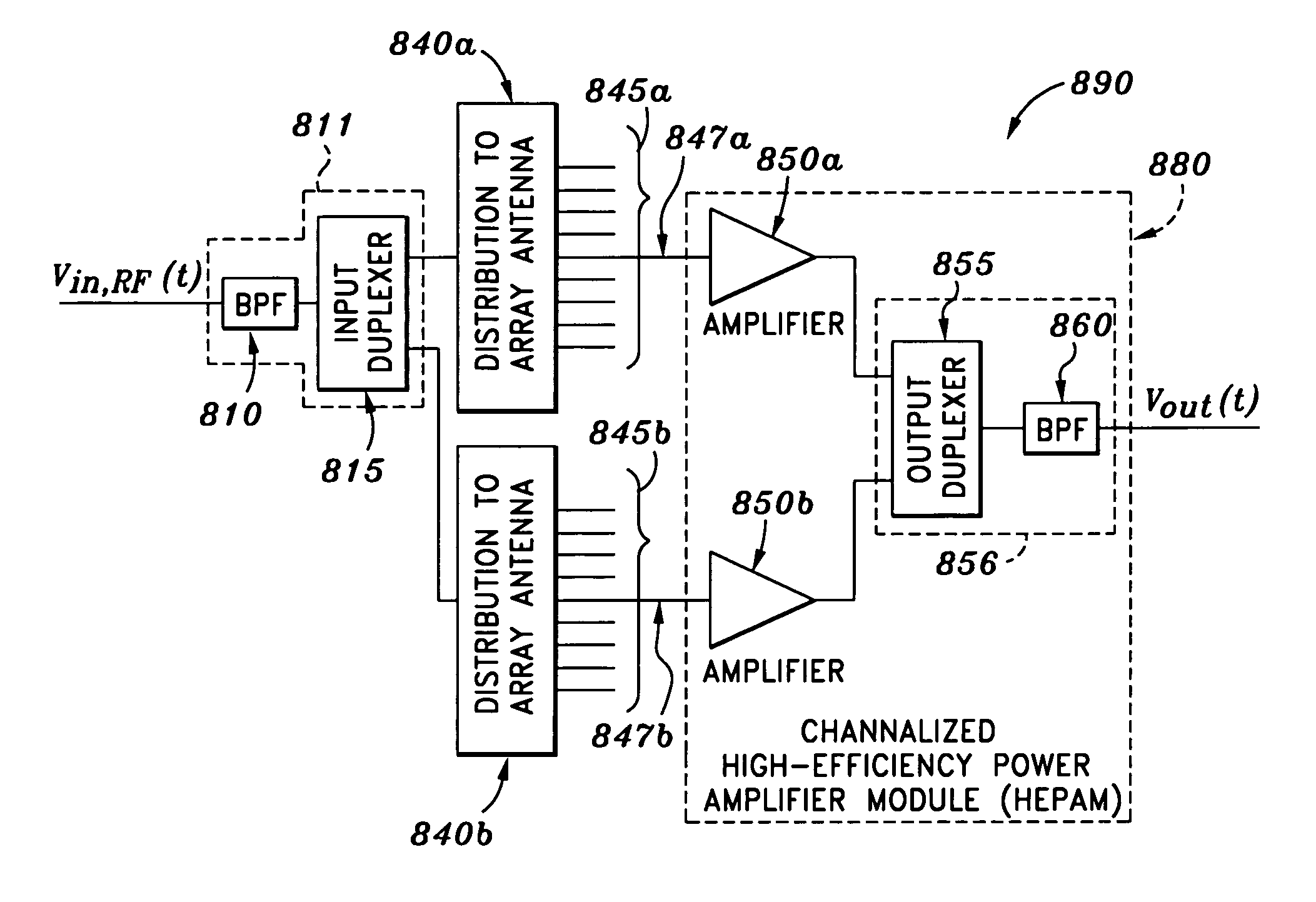
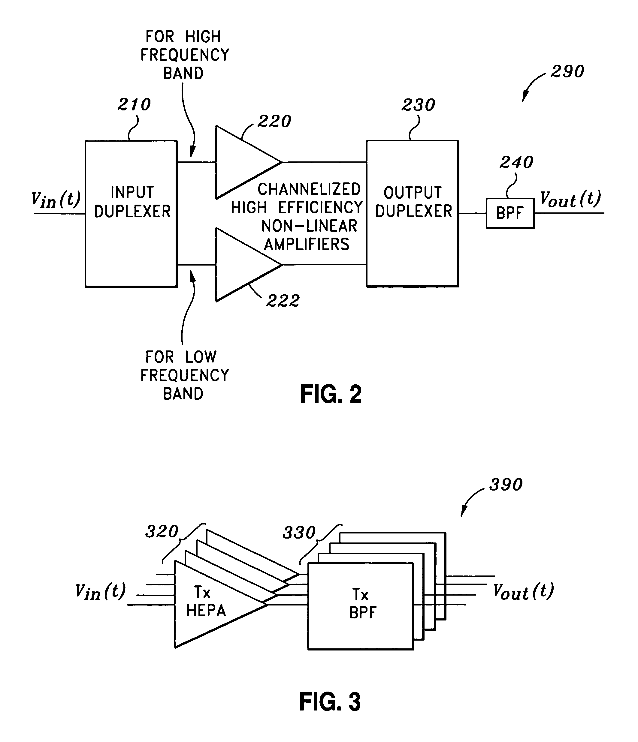
[0006]The present invention provides methods and systems for suppressing out-of-band emissions at the outputs of non-linear amplifiers. According to one embodiment of the present invention, appropriate filters and diplexers are used to control spectral re-growth. A high level of spectral re-growth suppression is possible using channelized highly efficient non-linear power amplifiers. Accordingly, the production of inter-modulation frequency components generated by non-linear amplification is reduced. According to one embodiment, spectral shaping is applied to an input signal, and a light-duty filter is used after a transmit power amplifier.
[0007]The present invention can minimize transmit filter requirements and the number of cables and connectors. It can also provide thin profile, reduce weight, increase efficiency, reduce manufacturing cost and decrease RF loss.

Problems solved by technology

Furthermore, non-linear amplifiers cause spectral re-growth.
Methods to control spectral re-growth, such as using pre-distorter circuits or highly linear but less-efficient amplifiers have not sufficiently mitigated the problem.

Method used


Image

  • Channelized amplifier system and method
  • Channelized amplifier system and method
  • Channelized amplifier system and method

Examples


Embodiment Construction

[0028]In the following detailed description, numerous specific details are set forth to provide a full understanding of the present invention. It will be obvious, however, to one ordinarily skilled in the art that the present invention may be practiced without some of these specific details. In other instances, well-known structures and techniques have not been shown in detail not to obscure the present invention.

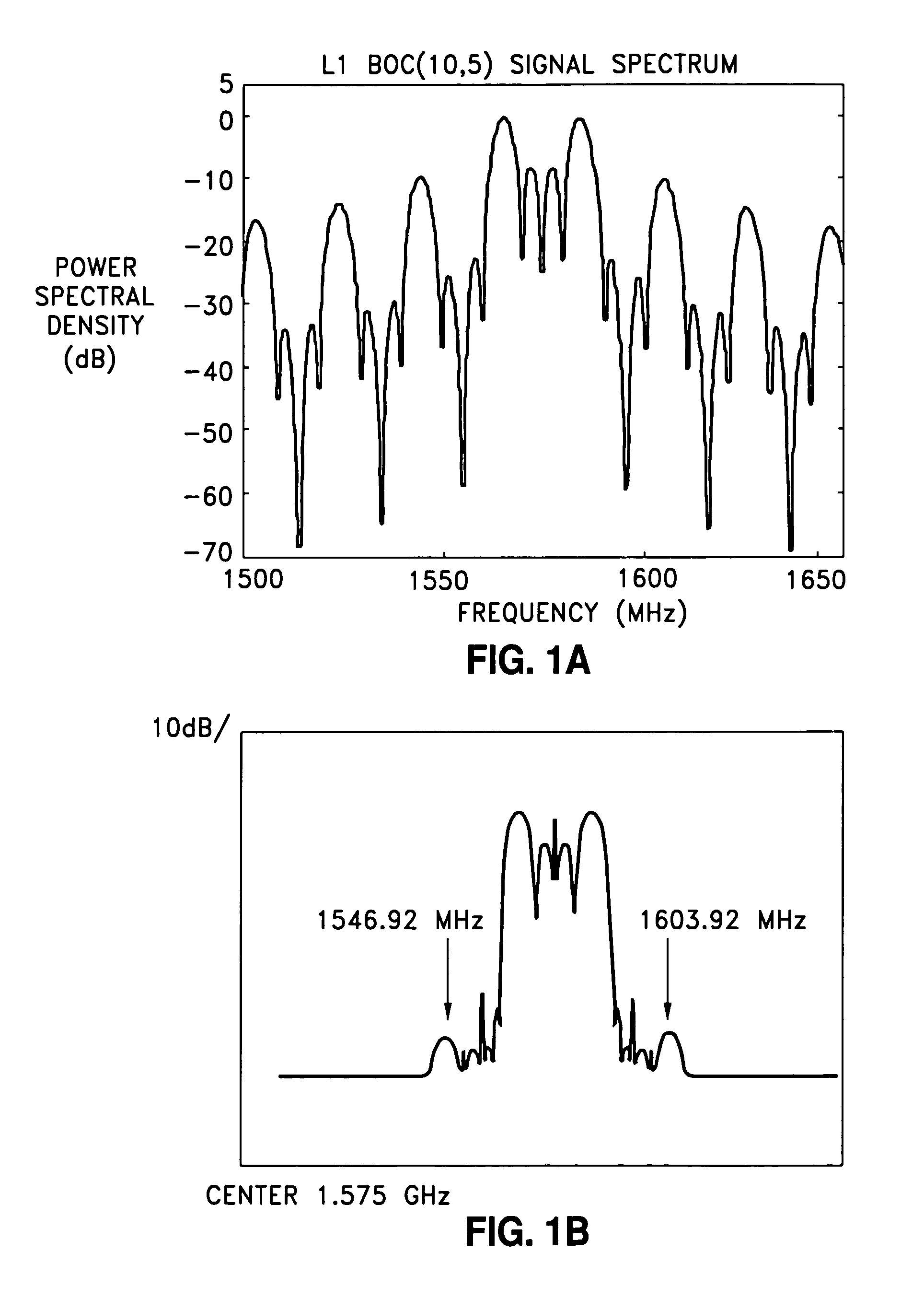
[0029]A Global Positioning System (GPS) satellite transmits a number of signals. A GPS system is required to protect a plurality of radio astronomy frequency bands from the RF transmissions from GPS satellites. One of the protected frequency bands is the 1610.6-1613.8 MHz band. This band is used by radio astronomers world wide for observing radio spectral emissions at 1612.231 MHz. Observations made in this band are important for characterizing OH-IR sources in space.

[0030]One of the GPS signals is the L1 BOC (10, 5) signal, which denotes a modulation format using a Binary ...


PUM


Abstract

A channelized amplification system and method for mitigating non-linear amplification effects and controlling spectral re-growth is disclosed. A system includes an input frequency divider for converting a first signal into a plurality of frequency band signals and a plurality of channelized high-efficiency non-linear power amplifiers coupled to the frequency divider. Each of the plurality of frequency band signals occupies a frequency band that is different from one another. The plurality of channelized high-efficiency non-linear power amplifiers receive and amplify the plurality of frequency band signals and produce a plurality of non-linearly amplified signals. The system further includes a frequency combiner coupled to the plurality of channelized high-efficiency non-linear power amplifiers. The frequency combiner combines the plurality of amplified signals and produce a second signal. The system further includes an output band-pass filter coupled to the frequency combiner. Each of the frequency divider and frequency combiner can be a duplexer or a diplexer when the number of the plurality of frequency band signals is two. The system further includes an input band-pass filter for spectrally shaping a signal and a distributor for distributing a signal to a plurality of amplification modules. Each of the amplification modules includes a corresponding frequency divider, a corresponding plurality of channelized high-efficiency non-linear power amplifiers, a corresponding frequency combiner and a corresponding output band-pass filter. The system further includes a radio frequency up-converter coupled to the input band-pass filter.

Description

CROSS-REFERENCE TO RELATED APPLICATION[0001]The present application claims the benefit of priority under 35 U.S.C. §119 from U.S. Provisional Patent Application Ser. No. 60 / 664,956 entitled “ENHANCED MITIGATION OF NON-LINEAR AMPLIFICATION EFFECTS,” filed on Mar. 25, 2005, the disclosure of which is hereby incorporated by reference in its entirety for all purposes.STATEMENT AS TO RIGHTS TO INVENTIONS MADE UNDER FEDERALLY SPONSORED RESEARCH OR DEVELOPMENT[0002]Not ApplicableFIELD OF THE INVENTION[0003]The present invention generally relates to electronic signal amplification and the emission of electromagnetic signals and, more particularly, relates to the suppression of out-of-band emissions at the outputs of non-linear amplifiers.BACKGROUND OF THE INVENTION[0004]A power amplifier is generally used to provide the final stage of amplification where the delivery of radio frequency (RF) power is required. Most power amplifiers, when pushed to deliver their maximum output power, produce ...

Claims


Application Information

Patent Timeline
Patent Type & Authority Patents(United States)
IPC IPC(8): H04B1/38
CPCH04B1/0483
Inventor LAM, LAWRENCE K.NGO, ALBERT T.
Owner LOCKHEED MARTIN CORP
Learn More