
Method and system for discovering network paths

Inactive Publication Date: 2010-07-20
GOOGLE LLC
View PDF10 Cites 112 Cited by
  • Summary
  • Abstract
  • Description
  • Claims
  • Application Information

AI Technical Summary

Benefits of technology

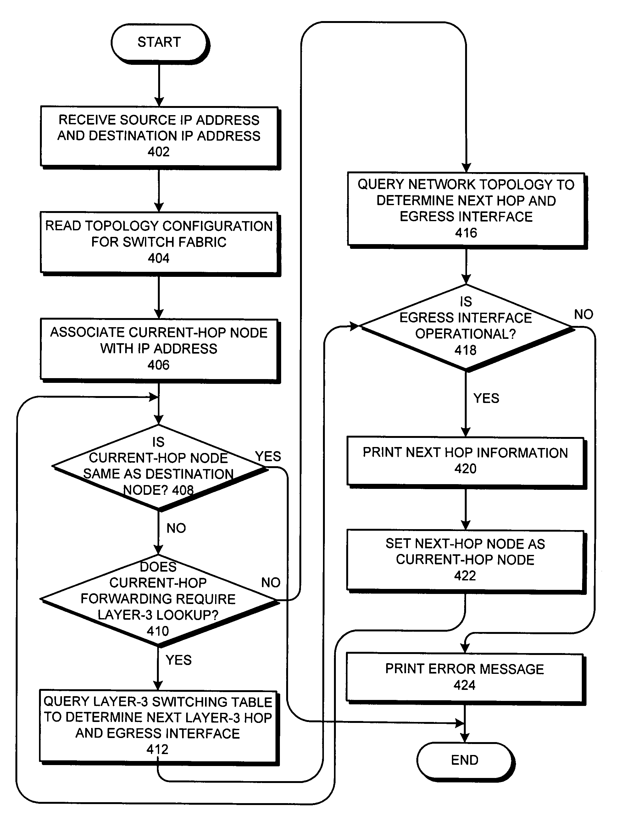
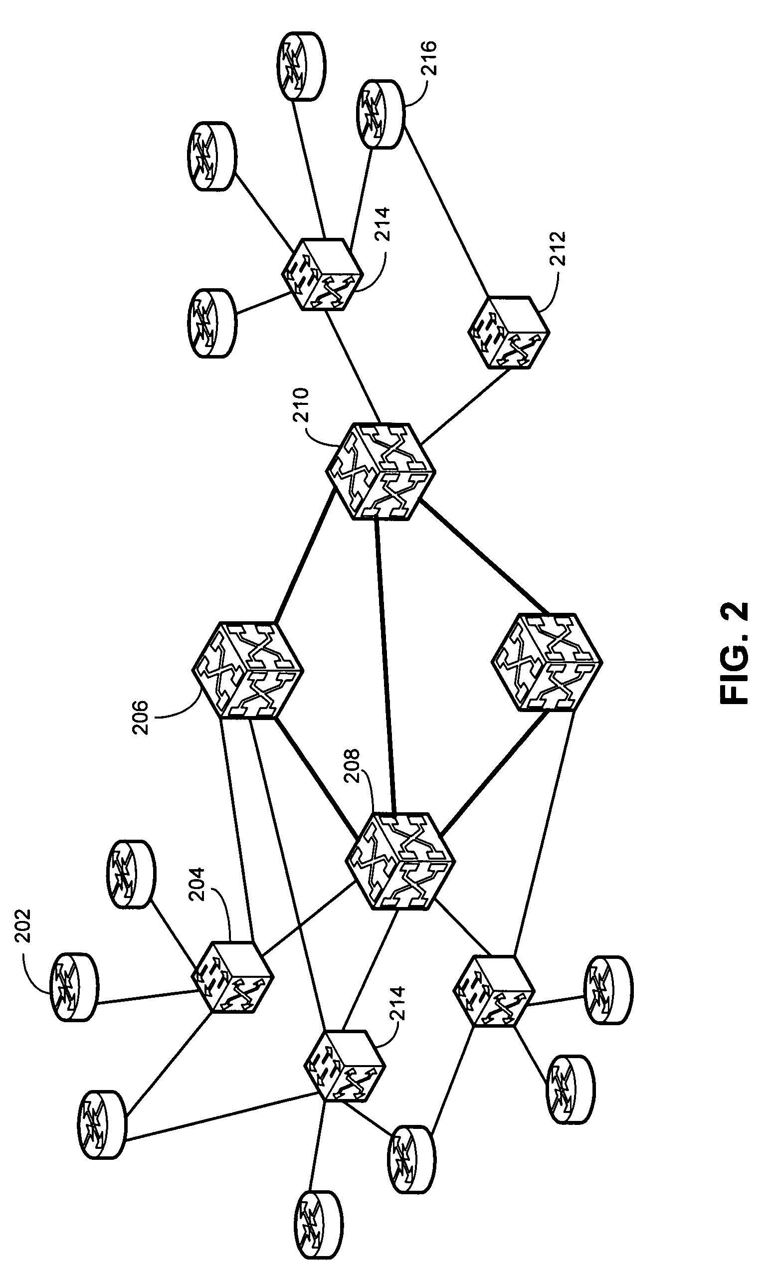
[0009]One embodiment of the present invention provides a system that identifies network switches along a path. During operation, the system receives an address of a source node and an address of a destination node. The system also maintains a set of topology information for a network which includes layer-3, layer-2, and sub-layer-2 switches. The system simulates a data packet originated at the source node and destined for the destination node. During the simulation, the system determines whether a current-hop node performs laye

Problems solved by technology

However, such heavy processing also imposes constraints on router speed.
Consequently, high-speed ports on an IP router are expensive, and building an entire server-farm network using only IP routers can be very costly.
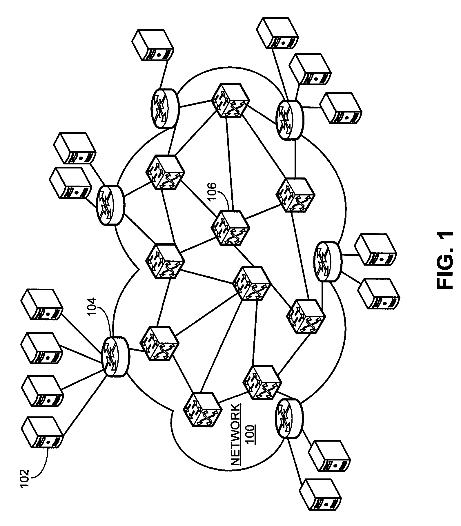
In a multi-tier network with layer-3, layer-2, and sub-layer-2 switches, however, the traceroute command becomes insufficient, because the switches operating below layer-3 are “invisible” to the traceroute command.

Method used


Image

  • Method and system for discovering network paths
  • Method and system for discovering network paths
  • Method and system for discovering network paths

Examples


Embodiment Construction

[0019]The following description is presented to enable any person skilled in the art to make and use the invention, and is provided in the context of a particular application and its requirements. Various modifications to the disclosed embodiments will be readily apparent to those skilled in the art, and the general principles defined herein may be applied to other embodiments and applications without departing from the spirit and scope of the present invention. Thus, the present invention is not limited to the embodiments shown, but is to be accorded the widest scope consistent with the claims.

[0020]The data structures and code described in this detailed description are typically stored on a computer-readable storage medium, which may be any device or medium that can store code and / or data for use by a computer system. This includes, but is not limited to, volatile memory, non-volatile memory, magnetic and optical storage devices such as disk drives, magnetic tape, CDs (compact dis...


PUM


Abstract

One embodiment of the present invention provides a system that identifies network switches along a path. During operation, the system receives an address of a source node and an address of a destination node. The system maintains a set of topology information for a network. The system further simulates a data packet originated at the source node and destined for the destination node. During the simulation, the system determines whether a current-hop node performs layer-3, layer-2, or sub-layer-2 switching. The system sends a query to the current-hop node over a separate control channel to determine the status of the current-hop node and discover a next-hop node. The system then receives a reply. The system determines the next-hop node based on the reply and sets the next-hop node as the current-hop node.

Description

BACKGROUND[0001]1. Field of the Invention[0002]The present invention relates to the design of digital networks. More specifically, the present invention relates to a method and system for discovering network paths which include both layer-2 and layer-3 switches.[0003]2. Related Art[0004]Hi-performance web sites often rely on “server farms”—hundreds of networked computers performing similar tasks—for scalability, reliability, and fast response time. Deploying these server farms typically requires the power of a high-speed, versatile network to provide reliable connectivity and sufficient bandwidth among the servers.[0005]Conventionally, servers are interconnected through IP routers which process packets on layer-3, or the IP layer. By processing every packet's IP header based on routing tables, IP routers provide flexibility and re-configurability. However, such heavy processing also imposes constraints on router speed. Consequently, high-speed ports on an IP router are expensive, an...

Claims


Application Information

Patent Timeline
IPC IPC(8): H04L12/26H04J1/16G06F11/00G08C15/00G01R31/08
CPCH04L41/12H04L45/02H04L45/123H04L45/26H04L41/344
Inventor CHEN, JUNONG, JOON SUANSIMMONS, JASON MARCSINGH, ARJUNWAKERLY, MICHAEL JOHN
Owner GOOGLE LLC
Learn More