
Correcting device to compensate for polarization distribution perturbations

a correction device and polarization distribution technology, applied in the field of correction devices, can solve the problems of inability to compensate inability to achieve full compensation for the perturbation of the polarization distribution over the cross section of the projection light beam, and inability to achieve the effect of reducing wavefront errors

Inactive Publication Date: 2010-07-13
CARL ZEISS SMT GMBH
View PDF11 Cites 4 Cited by
  • Summary
  • Abstract
  • Description
  • Claims
  • Application Information

AI Technical Summary

Benefits of technology

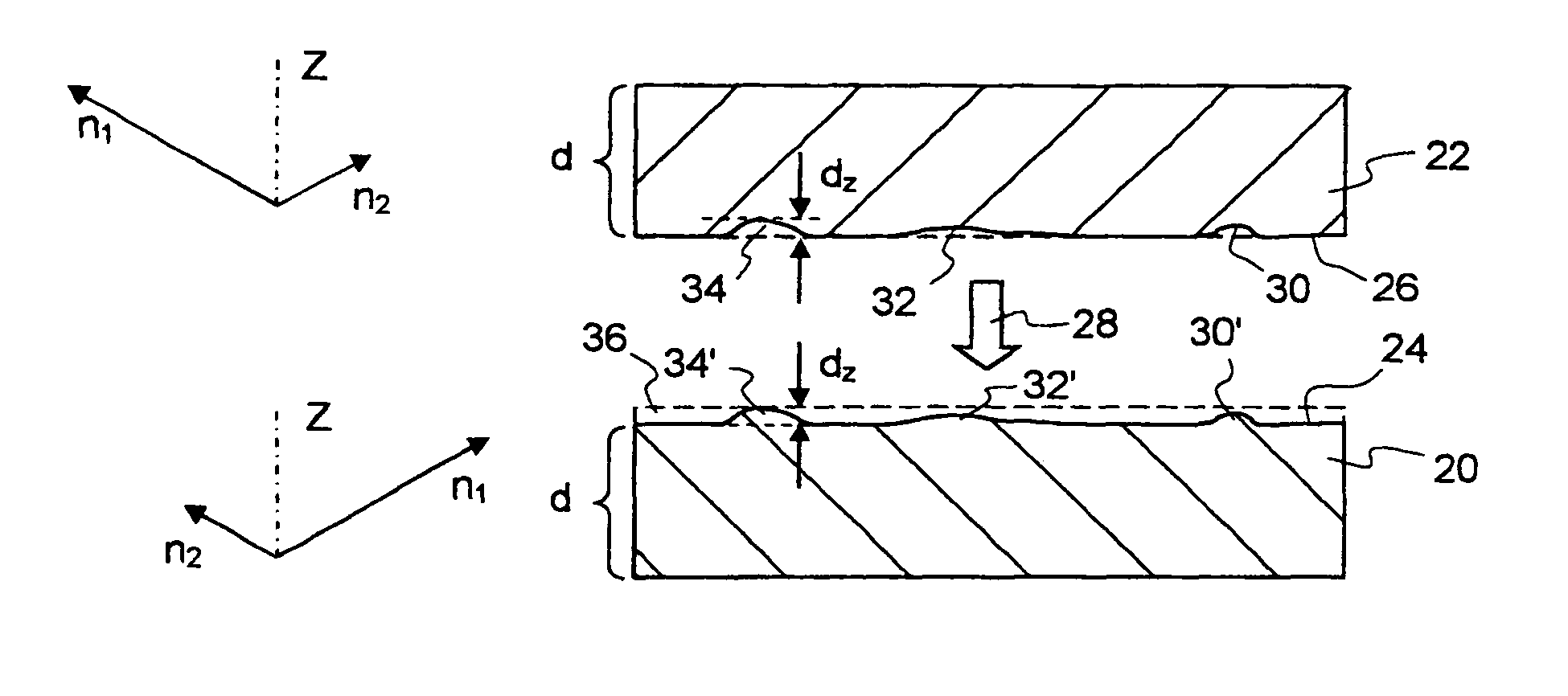
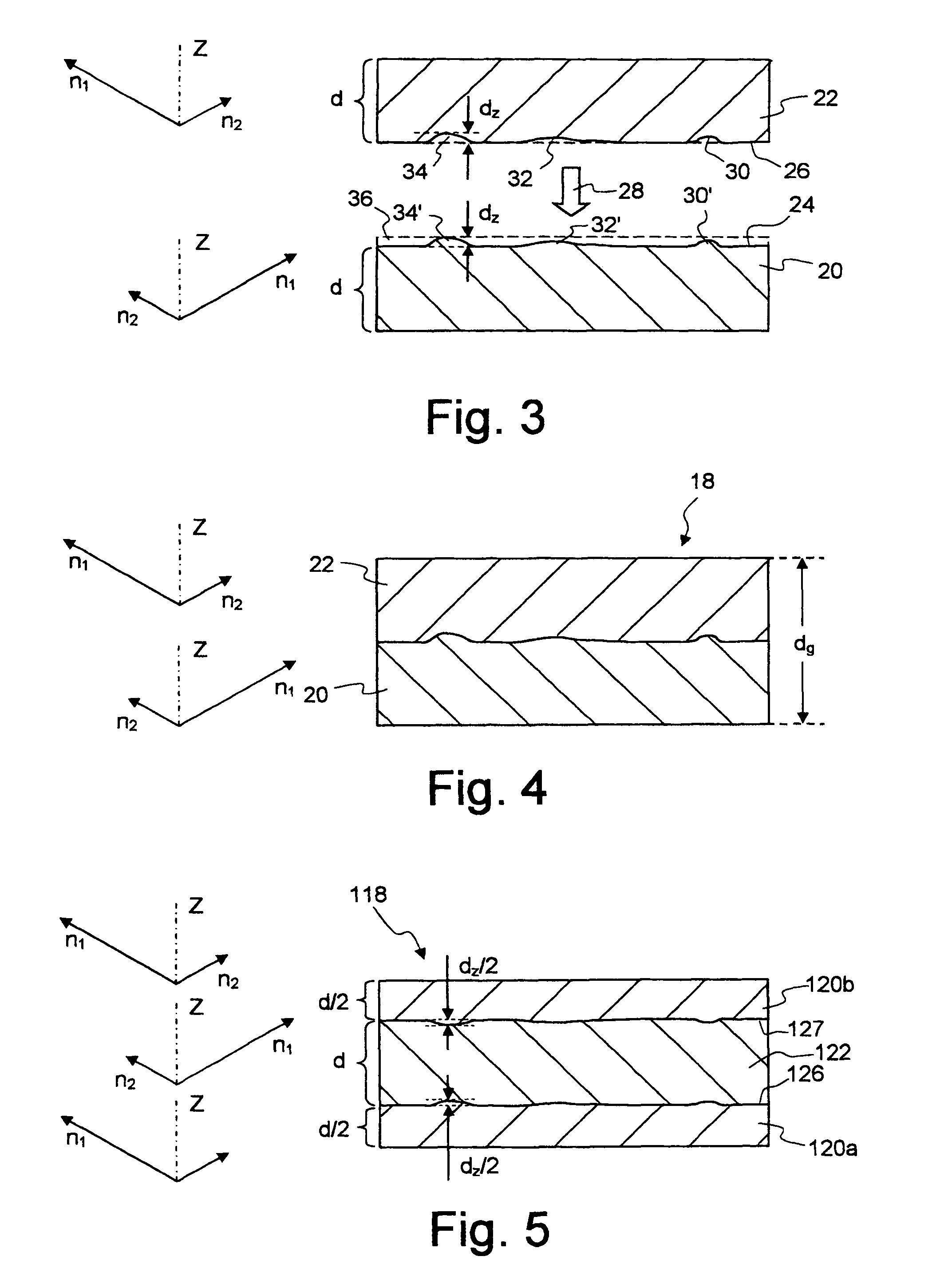
[0016]In a preferred configuration of the invention, the surfaces of the correcting elements are reprocessed complementarily with one another so that the total thickness of all the correcting elements of a correcting component is constant over its cross section. Since the correcting component as a whole does not have any thickness variations, wavefront errors are substantially avoided. This applies even if the individual correcting elements are not fastened directly to one another but are arranged at a distance from one another in the correcting device. If the correcting elements are flat disks, for example, then the overall correcting component acts as a plane-parallel plate which still locally influences the polarization but does not significantly influence the profile of the wavefront. Additional quartz plates, which are necessary in the prior art in order to equalize the optical path differences due to the thickness variations, can therefore be obviated.
[0017]In this configuration, it is furthermore advantageous that the local thickness variation required for the perturbation compensation at a particular point is thereby necessarily distributed between a plurality of correcting elements. If the correcting component comprises two correcting elements, for example, then the complementary reprocessing of the surfaces leads to a local thickness variation Δd being distributed between the two correcting elements so that the thickness of one correcting element is reduced by Δd / 2 at the corresponding point, and that of the other correcting element is increased by Δd / 2. Distributing the thickness variations between a plurality of correcting elements is advantageous particularly in the case of large thickness variations, since these can be accurately produced only with significant difficulties by the known reprocessing methods such as ion or atom beam etching.
[0020]Even with a total thickness of all the correcting elements which is constant over the cross section, however, slight wavefront errors due to the thickness variations of the individual correcting elements are not entirely avoidable. For this reason, it may be expedient for at least one correcting element to have a surface which is additionally reprocessed so as to reduce wavefront errors due to the thickness variations.
[0021]With only one correcting component, it is not possible to compensate for all types of polarization perturbations. Two correcting components are therefore provided in a preferred configuration of the invention, the birefringence axes of the correcting elements of one correcting component being rotated by 45° relative to the birefringence axes of the correcting elements of the other correcting component. In this way, it is possible to compensate not only for phase shifts but also for rotations of the polarization.

Problems solved by technology

If deviations from this defined polarization distribution occur, then this can lead to intolerable imaging errors and / or contrast losses in the image plane.
Although various measures for reducing the birefringence of fluorspar lenses are now known, full compensation for perturbations of the polarization distribution over the cross section of the projection light beam is nevertheless generally impossible.
If these perturbations remain uncompensated, then the contrast of the projection objectives is reduced, and this has an unfavorable effect on the size of the structures that can then be produced with such apparatus.
Since the thickness variations required for the compensation amount only to a few micrometers, the freeform surfaces on the plate cannot be produced by polishing or other conventional methods of material erosion.
A disadvantage with this known correcting device, however, is that the correcting plates do not only influence the polarization where perturbations are to be compensated for, but change the polarization over the entire cross section of the light beam.
Such correcting plates would be neither producible nor manageable.

Method used


Image

  • Correcting device to compensate for polarization distribution perturbations
  • Correcting device to compensate for polarization distribution perturbations
  • Correcting device to compensate for polarization distribution perturbations

Examples


Embodiment Construction

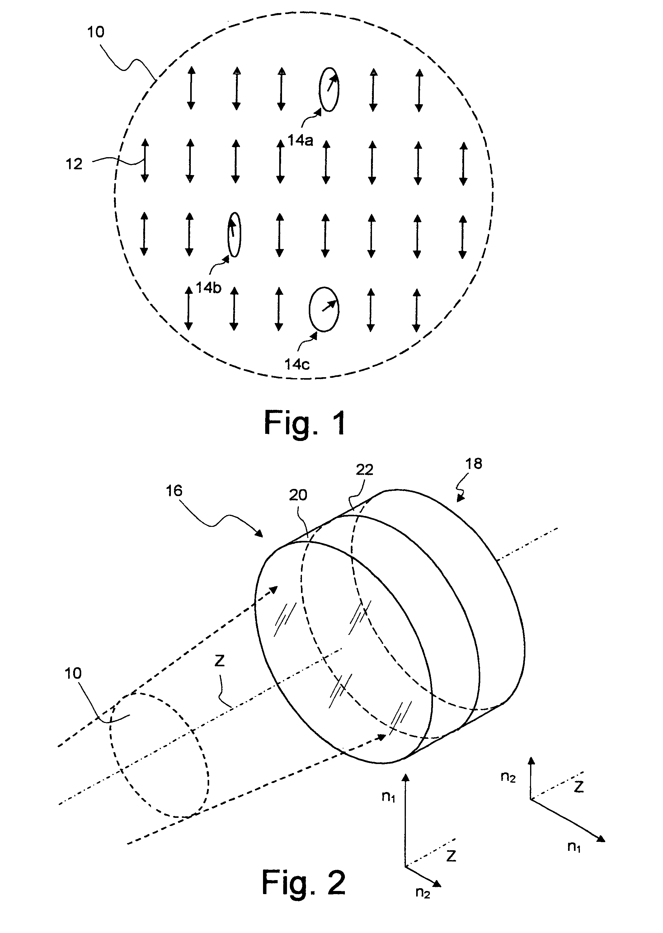
[0030]FIG. 1 shows a cross section through a light beam 10, in which a polarization distribution is schematically indicated with the aid of arrows 12. The arrows 12 are intended to represent the polarization direction inside the light beam 10. As can be seen in FIG. 1, the light is mostly polarized linearly with the same polarization direction over the cross section of the light beam 10. At a few points which are denoted by 14a, 14b and 14c in FIG. 1, however, the light is polarized not exactly linearly but more or less elliptically. These perturbations of the polarization distribution may lead, in subsequent polarization-selective optical elements such as beam-splitter layers or retardation plates, to intolerable imaging errors and / or to a contrast loss in the image plane.

[0031]In a perspective representation which is not true to scale, FIG. 2 shows a correcting device 16 with which it is possible to compensate for the perturbations 14a, 14b and 14c in the polarization distribution...


PUM

PropertyMeasurementUnit
wavelengthsaaaaaaaaaa
thicknessesaaaaaaaaaa

Abstract

A corrective device for compensating disturbances of polarization distribution across the cross section of a light beam (10). The corrective device includes a corrective member (18; 118) encompassing two double refractive corrective elements (20, 22; 120a, 120b, 122; 220; 222; 320, 322) with two substantially parallel surfaces (24, 26; 126, 127). The thickness (d) of the corrective element (22; 122, 222) is essentially constant between the surfaces (26; 126, 127). At least one of the surfaces (24, 26; 126, 127) of at least one of the corrective elements (20, 22; 120a, 120b, 122; 220; 222; 320, 322) is refinished in such a way that local irregularities in thickness Δd are created, by which the disturbances of polarization distribution are at least nearly compensated. The arrangement, thickness (d), and double-refractive properties of the corrective elements (20, 22; 120a, 120b, 122; 220; 222; 320, 322) are selected such that the double-refractive effects thereof mutually cancel each other out if the local irregularities in thickness Δd are not taken into consideration. The corrective device influences polarization only at points where disturbances are to be compensated.

Description

CROSS-REFERENCE TO RELATED APPLICATIONS[0001]This is a National Stage of International Application No. PCT / EP2004 / 006504 filed Jun. 17, 2004, and claiming priority of German patent application DE 103 28 938.0. The full disclosure of the International Application is hereby incorporated herein by reference.BACKGROUND OF THE INVENTION[0002]1. Field of the Invention[0003]The invention relates to a correcting device to compensate for perturbations of the polarization distribution over the cross section of a light beam in an optical system, for example a projection objective for a microlithographic projection exposure apparatus.[0004]2. Description of Related Art[0005]A correcting device and a projection objective of this type are known from DE 198 07 120 A1 (the U.S. counterpart of which is patented as U.S. Pat. No. 6,252,712 to Fuerter et al.).[0006]In many optical systems, a prerequisite for a high imaging quality is that the light passing through the optical system should be in a defi...

Claims


Application Information

Patent Timeline
Patent Type & Authority Patents(United States)
IPC IPC(8): G02B5/30G02B13/14G02B17/08G02B27/00G02B27/28G03F7/20
CPCG02B1/08G02B5/3083G02B17/0892G02B27/286G03F7/70308G03F7/70566G03F7/70966G02B17/08
Inventor HEMBD, CHRISTIAN
Owner CARL ZEISS SMT GMBH
Learn More