
Current limited voltage supply

a current limit and voltage supply technology, applied in the field of integrated circuits, can solve the problems of adversely affecting the operation of the integrated circuit device, circuitry present within the standard digital logic, and high power consumption, and achieve the effect of minimizing voltage fluctuations and sufficient energy

Active Publication Date: 2010-07-13
SEMICON COMPONENTS IND LLC
View PDF8 Cites 0 Cited by
  • Summary
  • Abstract
  • Description
  • Claims
  • Application Information

AI Technical Summary

Benefits of technology

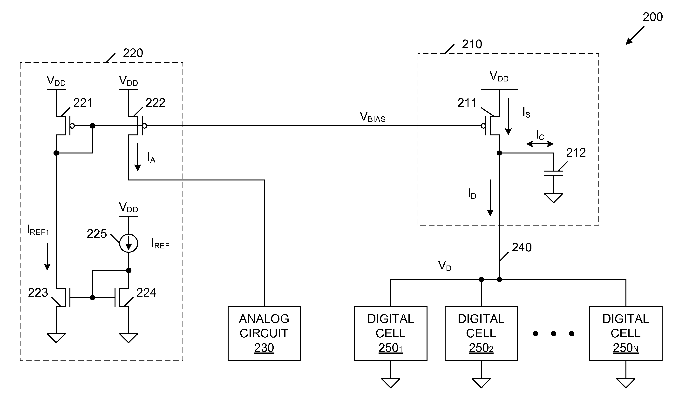
The present invention provides a current limited voltage supply for powering digital logic cells of an integrated circuit. It includes a transistor and a capacitor in a current mirror configuration with a bias circuit, which provides a limited supply current. The limited supply current is used to charge the capacitor while the digital logic cells are not switching. However, while the digital logic cells are switching, the capacitor discharges to the digital logic cells, thereby providing them with sufficient energy to implement high-speed switching. The capacitor also minimizes voltage fluctuations within the current limited voltage supply, so that analog circuitry can be reliably powered from a different branch of the same current mirror circuit.

Problems solved by technology

As a result, relatively high switching currents will flow through the standard digital logic cells during normal operating conditions, thereby leading to high power consumption.
The high switching currents flowing through the standard digital logic cells may also cause noise to be introduced to the power supply lines of the integrated circuit device, thereby adversely affecting operation of the integrated circuit device.
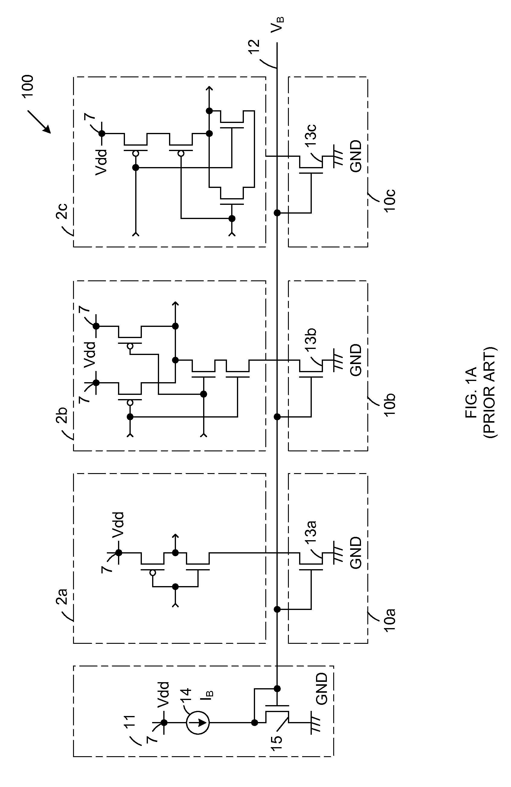
However, if the current flowing from each of the standard digital logic cells 2a-2c to ground is limited too much, then the circuitry present within the standard digital logic cells 2a-2c may not operate correctly (i.e., may not be capable of switching at the desired frequency).
Thus, the effectiveness of variable current sources 10a-10c is limited.
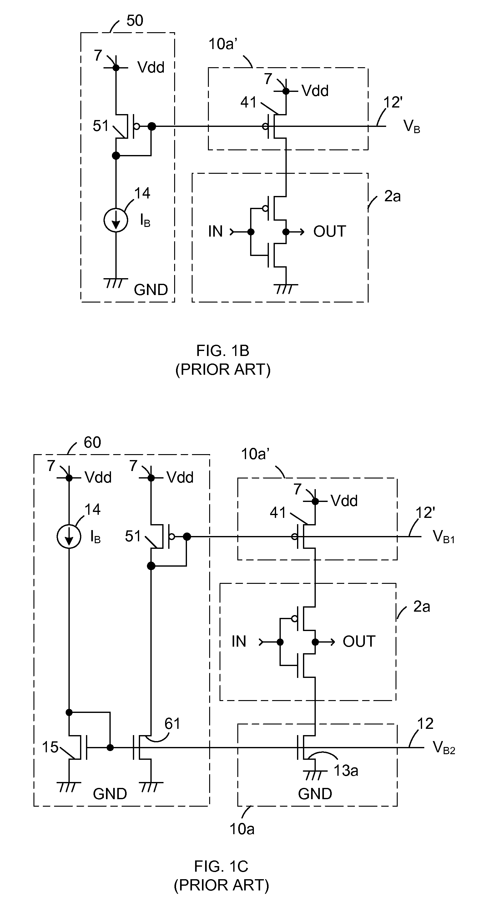
However, the circuit of FIG. 1B exhibits the same deficiencies as the circuit of FIG. 1A.
However, the circuit of FIG. 1C exhibits the same deficiencies as the circuit of FIG. 1A.

Method used


Image

  • Current limited voltage supply
  • Current limited voltage supply
  • Current limited voltage supply

Examples


Embodiment Construction

[0013]FIG. 2 is a circuit diagram of a semiconductor integrated circuit (IC) chip 200 in accordance with one embodiment of the present invention. IC chip 200 includes a current limited voltage supply 210, a bias circuit 220, analog circuit 230, digital cell supply line 240 and standard digital logic cells 2501-250N. Digital logic cells 2501-250N may include, for example, inverters and / or logic gates, which have output signals that switch between logic states in response to one or more input signals. Each of the digital logic cells 2501-250N is coupled between the digital cell supply line 240 and ground. As described in more detail below, the digital supply line 240 receives a supply current ID from the current limited voltage supply 210. A voltage VD is developed on the digital supply line 240.

[0014]In accordance with one embodiment, current limited voltage supply 210 includes a P-channel MOS transistor 211 and an integrated capacitor 212. The source of P-channel MOS transistor 211 ...


PUM


Abstract

A current limited voltage supply including a transistor and a capacitor is provided for powering digital logic cells of an integrated circuit. The transistor is connected in a current mirror configuration, such that a constant reference current is mirrored through the transistor to create a first supply current. The transistor is coupled to the digital logic cells and the capacitor. The first supply current is used to charge the capacitor while the digital logic cells are not switching. While the digital logic cells are switching, the capacitor discharges to the digital logic cells, thereby providing the digital logic cells with sufficient energy to implement high-speed switching. The capacitor minimizes voltage fluctuations within in the current limited voltage supply, such that analog circuitry can be reliably powered from a different branch of the same current mirror circuit.

Description

FIELD OF THE INVENTION[0001]The present invention relates to integrated circuits using standard CMOS technology. More specifically, the present invention relates to an integrated circuit having a current limited voltage supply.RELATED ART[0002]In conventional semiconductor integrated circuit devices, standard digital logic cells are designed to have an output driving capability sufficient to drive an output signal at a selected frequency under worst-case load conditions. As a result, relatively high switching currents will flow through the standard digital logic cells during normal operating conditions, thereby leading to high power consumption. The high switching currents flowing through the standard digital logic cells may also cause noise to be introduced to the power supply lines of the integrated circuit device, thereby adversely affecting operation of the integrated circuit device. To help alleviate these problems, variable current sources have been coupled to standard digital...

Claims


Application Information

Patent Timeline
Patent Type & Authority Patents(United States)
IPC IPC(8): H03K17/16H03K19/003
CPCG05F1/56
Inventor DUMITRU, IULIANRADOIAS, LIVIU-MIHAIMANCIOIU, MARILENA
Owner SEMICON COMPONENTS IND LLC
Learn More