Methods and apparatus for image reconstruction

a technology of image reconstruction and apparatus, applied in the field of image reconstruction, can solve the problems of image artifact production, inaccurate location of patient tables, and image artifact generation

Inactive Publication Date: 2010-06-08
GENERAL ELECTRIC CO
View PDF20 Cites 3 Cited by
  • Summary
  • Abstract
  • Description
  • Claims
  • Application Information

AI Technical Summary

Problems solved by technology

The disadvantage of the helical mode, on the other hand, is the production of image artifacts.
In practice, however, due to technical limitations the patient table location may not be known accurately.
However image artifacts may be generated if the table does not index at a constant speed.

Method used


Image

  • Methods and apparatus for image reconstruction
  • Methods and apparatus for image reconstruction
  • Methods and apparatus for image reconstruction

Examples


Embodiment Construction

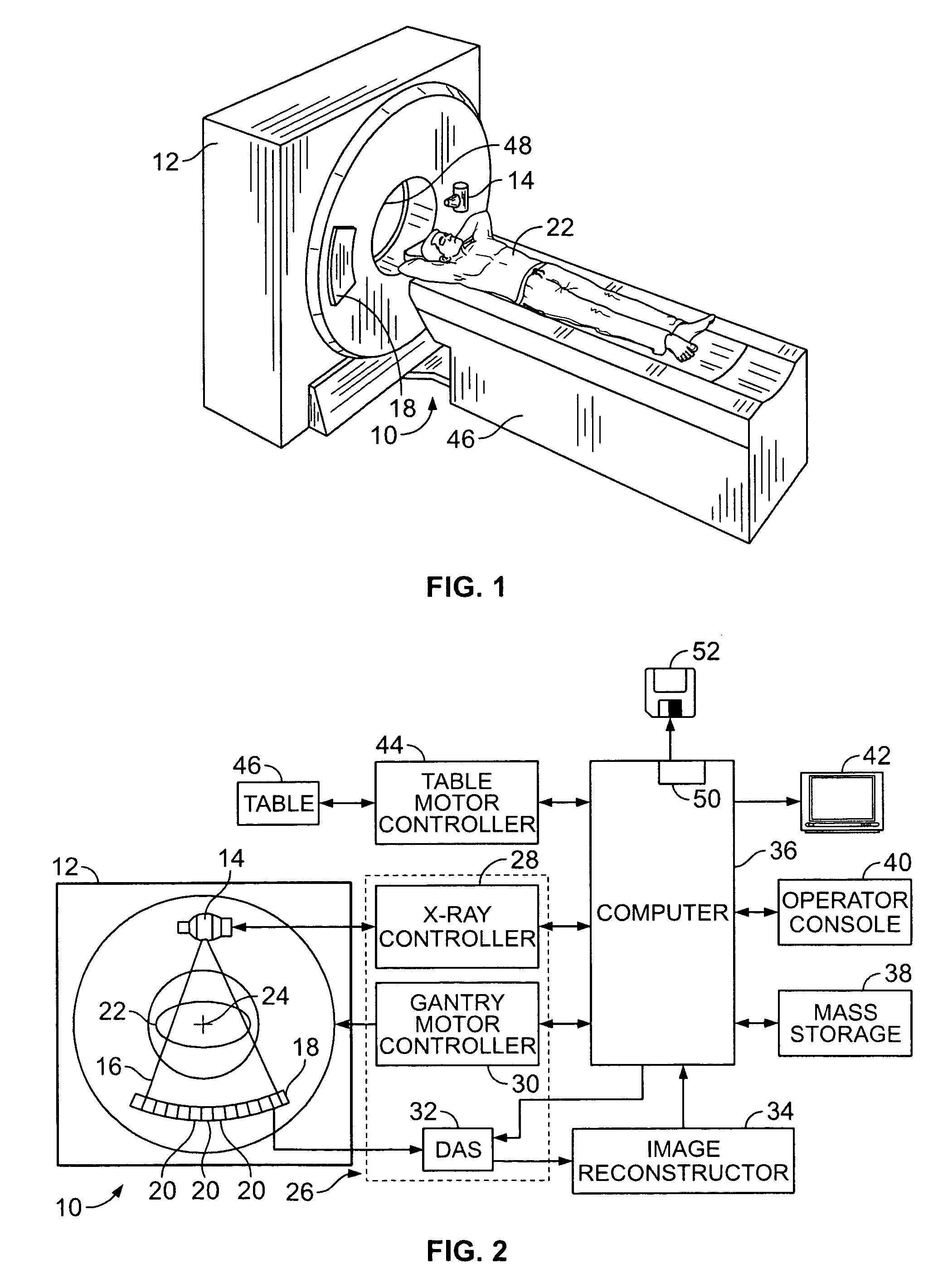
[0013]In some known CT imaging system configurations, an x-ray source projects a fan-shaped beam which is collimated to lie within an X-Y plane of a Cartesian coordinate system and generally referred to as an “imaging plane”. The x-ray beam passes through an object being imaged, such as a patient. The beam, after being attenuated by the object, impinges upon an array of radiation detectors. The intensity of the attenuated radiation beam received at the detector array is dependent upon the attenuation of an x-ray beam by the object. Each detector element of the array produces a separate electrical signal that is a measurement of the beam intensity at the detector location. The intensity measurements from all the detectors are acquired separately to produce a transmission profile.

[0014]In third generation CT systems, the x-ray source and the detector array are rotated with a gantry within the imaging plane and around the object to be imaged such that the angle at which the x-ray beam ...


PUM


Abstract

Methods and apparatus for producing an image of an object with a multi-slice imaging apparatus having a row of detectors are provided. The method includes generating a first partial image using projection data acquired at a first imaging position in a step-and-shoot imaging mode, generating a second partial image using projection data acquired at a second imaging position, and combining the partial images to form a final image.

Description

CROSS REFERENCE TO RELATED APPLICATIONS[0001]This application claims priority to U.S. provisional patent application with Ser. No. 60 / 613,997, filed on Sep. 28, 2004, and hereby incorporated by referenced in its entirety.BACKGROUND OF THE INVENTION[0002]This invention relates generally to the reconstruction of images and more particularly to methods and apparatus for reconstruction of step-and-shoot CT images using partial image data from adjacent scan positions.[0003]Typical multi-slice CT protocols utilize a helical mode for head scans. The advantages of the helical scans are the ability to reconstruct images at arbitrary locations and the elimination of inter-scan delays. The disadvantage of the helical mode, on the other hand, is the production of image artifacts. When the patient table moves during data acquisition, projection interpolation may be performed to estimate projection samples at the reconstruction location. The interpolation process assumes that the patient table lo...

Claims


Application Information

Patent Timeline
Patent Type & Authority Patents(United States)
IPC IPC(8): G06K9/00
CPCG06T11/006A61B6/027
Inventor HSIEH, JIANGDONG, FANG FRANKMYERS, THOMAS JOHNSEIDENSCHNUR, GEORGECONRY, ANNE MARIESOPCAK, ZACHARY WILLIAMGREKOWICZ, BRIAN
Owner GENERAL ELECTRIC CO
Why Eureka
Try Eureka