
AC-coupled equivalent series resistance

a series resistance and ac-coupled technology, applied in the direction of electric variable regulation, process and machine control, instruments, etc., can solve the problems of system instability, unavoidable poles and zeros, negative feedback, etc., to improve the stability of the feedback loop in the control circuit, improve the stability over a broader range of input frequencies, and the effect of greater flexibility in component choi

Active Publication Date: 2010-05-18
ANALOG DEVICES INC
View PDF14 Cites 14 Cited by
  • Summary
  • Abstract
  • Description
  • Claims
  • Application Information

AI Technical Summary

Benefits of technology

The present invention provides a control circuit and method that improves the stability of feedback loops in control circuits. This allows for greater flexibility in component choice and improved stability over a broader range of input frequencies. The control circuit includes a negative feedback control loop with an output stage and an associated ESR. A sub-circuit emulates a second ESR at a desired frequency. The method involves amplifying a signal back into an amplifying device to produce a negative feedback control loop with a characteristic transfer function. The ESR is emulated within the control loop to introduce a zero into the transfer function at a desired frequency.

Problems solved by technology

Nevertheless, because the output is fed back in a manner that reduces the system gain, the result is negative feedback, sometimes called degenerative feedback.
This is problematic when the system is operating at greater than unity gain as positive feedback will drive the system to an unstable oscillatory state.
Unwanted or unavoidable poles and zeros can create significant challenges when trying to stabilize a control system over a range of operating frequencies.
Previously, efforts have been made to stabilize a control system by designing the system so that troublesome poles only affect the system negligibly over the operating frequency range.
This approach limits the designer to specific component values and configurations.
For this reason, small variations in the value of the ESR in an output capacitor can have a significant destabilizing effect on the entire system.
In other words, it is the current that the system consumes when no load current is being supplied.
A drawback of this stabilization method is that a higher quiescent current drains the batteries that power the system.

Method used


Image

  • AC-coupled equivalent series resistance
  • AC-coupled equivalent series resistance
  • AC-coupled equivalent series resistance

Examples


Embodiment Construction

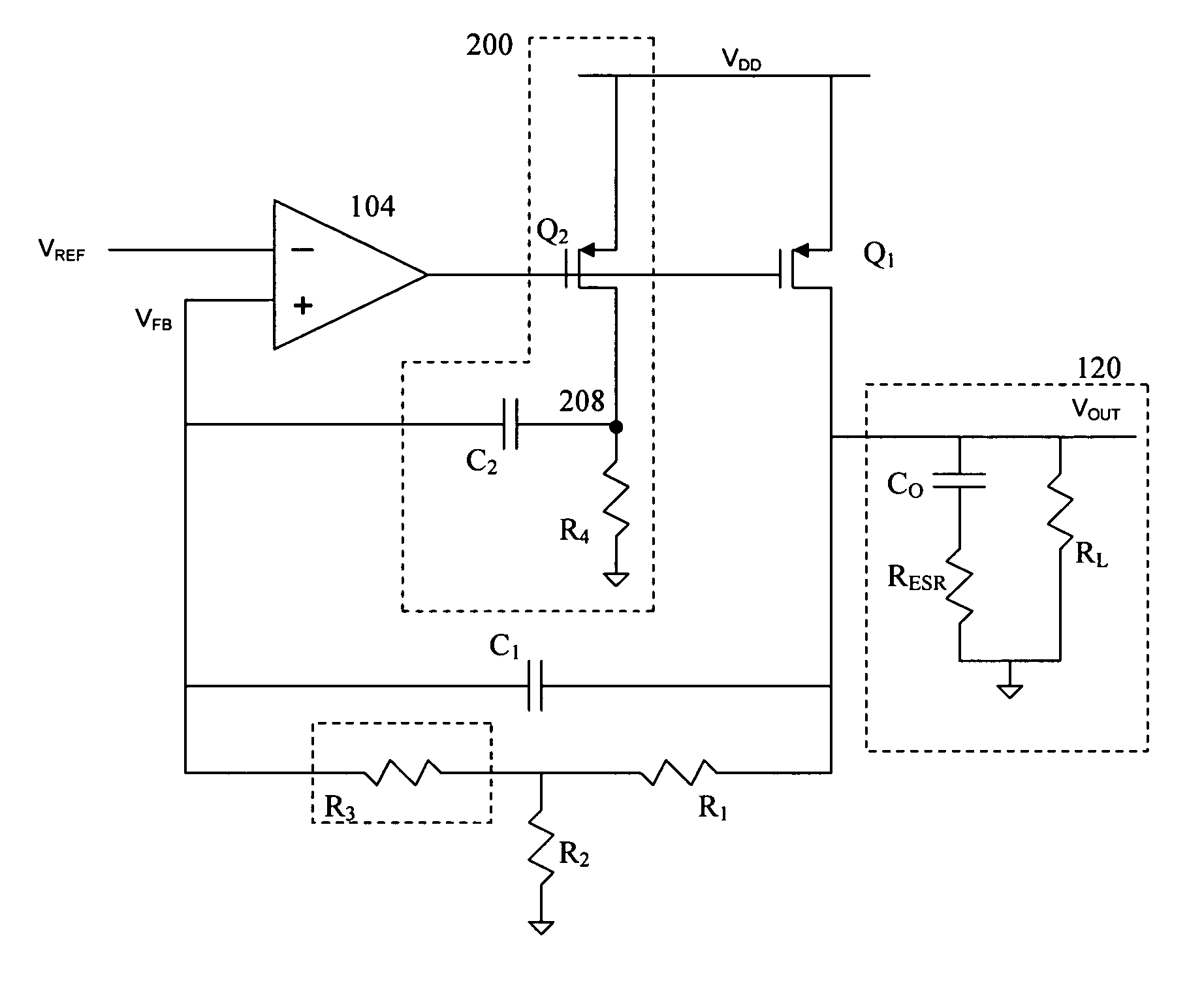
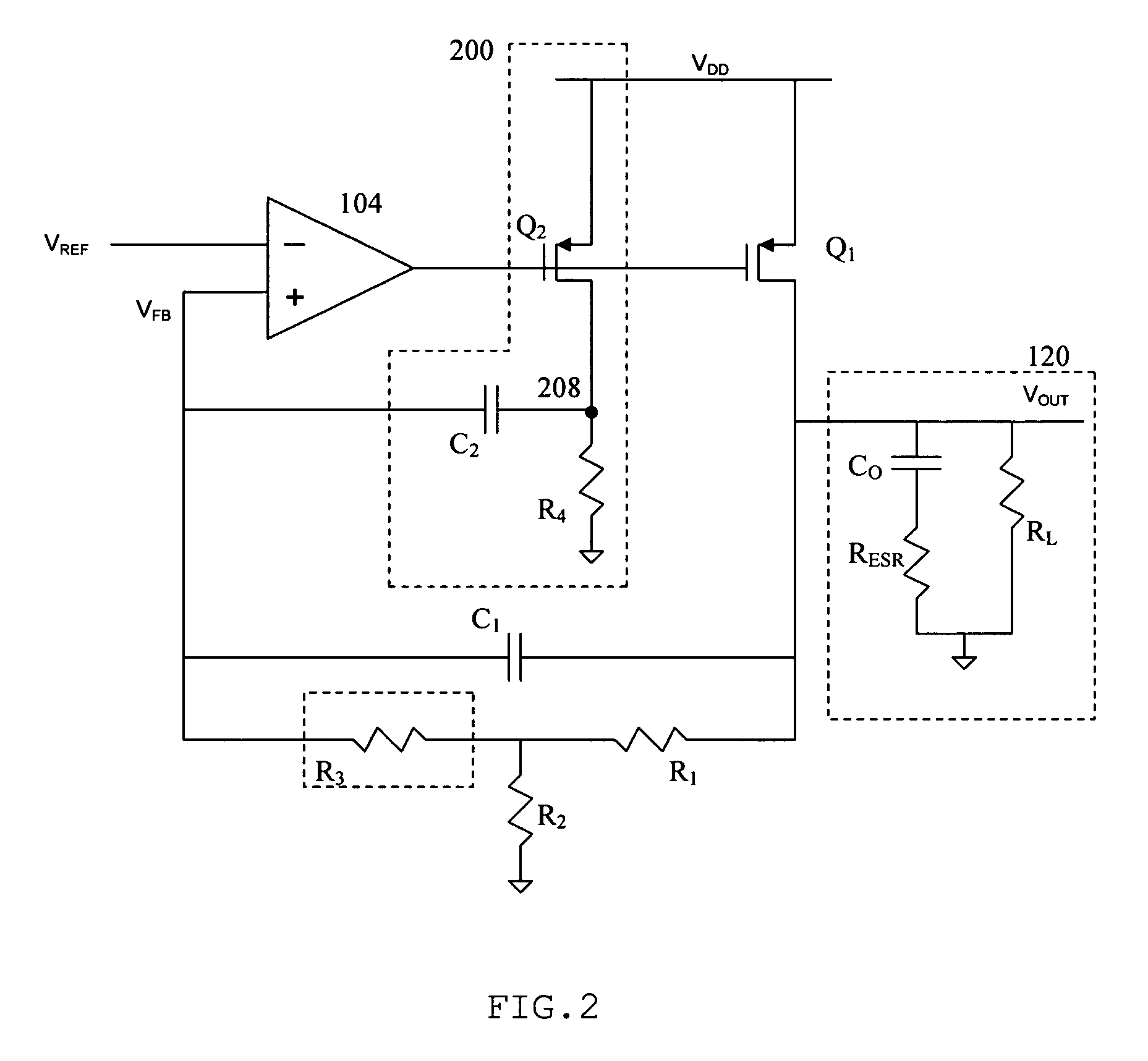
[0020]FIG. 2 illustrates one embodiment of a novel control circuit. The control circuit exhibits improved stability over the prior art for a broad range of input frequencies by emulating an ESR within the circuit and adding a zero to the transfer function at a desired frequency. The design is more immune to variations in the actual ESR of the output capacitor and other board parasitic elements such as trace inductance in series with the output capacitor. The control circuit is designed to drive a wide variety of load circuits. Some examples of such load circuits are a processor, an amplifier, a digital to analog converter or a pulse width modulation switching regulator.

[0021]The control circuit shown in FIG. 2 is an LDO regulator application with an additional emulated ESR that is AC-coupled into the system control loop to stabilize the system. The sub-circuit 200 is an example of one circuit that may be used to emulate the additional ESR.

[0022]In this embodiment sub-circuit 200 com...


PUM


Abstract

AC-coupled equivalent series resistance (ESR) is introduced into a control circuit to provide additional stability in the feedback control loop. A sub-circuit emulates the effect of a higher value ESR in the output capacitor. The additional ESR in the feedback control loop inserts a zero into the transfer function that describes the circuit response at a desired frequency. The added zero compensates for the effects of unwanted or unavoidable poles in the transfer function, allowing for a greater range of input signal frequencies.

Description

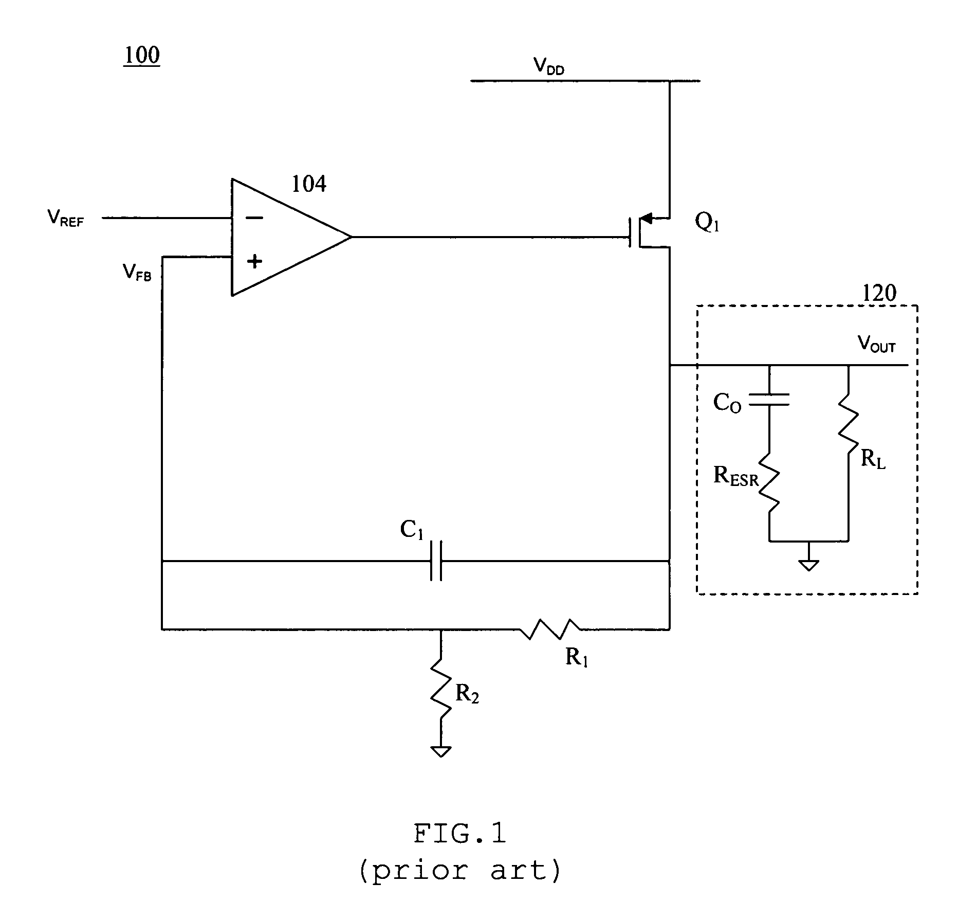
BACKGROUND OF THE INVENTION[0001]1. Field of the Invention[0002]The present invention relates generally to modern control systems and, more particularly, to negative feedback loops in such systems.[0003]2. Description of the Art[0004]FIG. 1 illustrates a known control system utilizing a negative feedback loop in a low drop-out (LDO) amplifier application 100. This particular application 100 is configured as an LDO regulator circuit. An LDO regulator is a circuit that provides a well-specified and stable DC voltage. The lowest value of differential (input / output) voltage at which the control loop stops regulating is called the dropout voltage. Modern applications such as communication electronics and other battery-powered portable devices require a low dropout voltage and low quiescent currents for increased power efficiency. LDO regulators meet both of these design needs.[0005]At the input stage, a reference input signal VREF is fed into the inverting input of a dual stage amplifier...

Claims


Application Information

Patent Timeline
Patent Type & Authority Patents(United States)
IPC IPC(8): G05F1/00
CPCG05F1/46
Inventor DEAN, JAMES ROBERT
Owner ANALOG DEVICES INC
Learn More