
Fiber optic radio frequency distribution system

a fiber optic radio frequency distribution and fiber optic technology, applied in the field of shipboard communication systems, can solve the problems of one-for-one, stovepiped connection schemes, and inability to allow flexibility of onboard radio frequency (rf) systems

Inactive Publication Date: 2010-05-11
LOCKHEED MARTIN CORP
View PDF12 Cites 32 Cited by
  • Summary
  • Abstract
  • Description
  • Claims
  • Application Information

AI Technical Summary

Benefits of technology

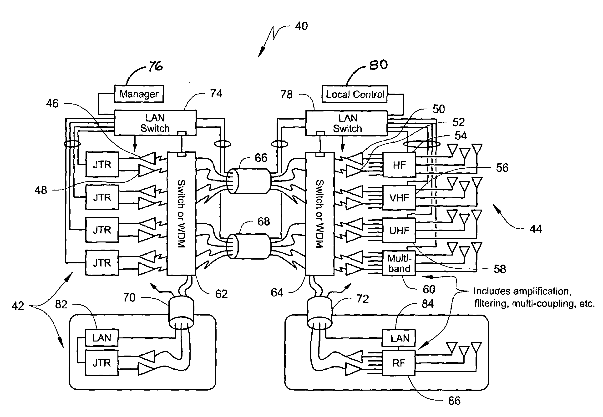
[0006]The present invention is directed to a scalable, flexible, automated radio frequency distribution system (FORFDS) using fiber optics to eliminate the need for metallic / coaxial type interconnections between onboard radios and antennas. Key elements of a FORFDS may include, for example, 1) electrical to optical conversion (and vice versa) of RF signals; 2) optical switching; 3) automated control and monitoring, including Ethernet interfaces; and 4) high density packaging. The system most preferably is compatible with JTRS (2 MHz to 2000 MHz), is scalable and cost effective (no longer in the laboratory or concept high cost ranges), compared with known technologies.
[0007]According to one embodiment, a fiber optic RF distribution system (FORFDS) suitable for both shipboard and fixed site applications, includes a fiber optic feed distribution between a communications center and antenna systems, fiber optic based switching for flexible communications, and software automation and control. The FORFDS provides a scalable interconnect capability for RF signals with the ability to distribute RF signals between radio channels and the antenna interconnect system. The FORFDS architecture provides a high bandwidth infrastructure of RF and digital data connectivity to between shipboard spaces to support current and future JTRS interface requirements. Further, distribution of fiber optic cabling at multiple points within a ship, such as provided by the Integrated Communications and Network (ICAN) blown-fiber system, the JTRS can be distributed within multiple spaces on a ship, thus improving survivability against catastrophic events, among other things.
[0008]The architecture associated with the fiber optic RF distribution system includes photonic switching by using mechanical and / or Wave Division Multiplex (WDM) implementation. The location of the switching components are dependant on the installation requirements, and may include switching co-located with the JTR set and / or co-located with the RF antenna interface components. The location of the switching system with the JTR set supports concentration of the fiber signals from remote locations. Conversely, location of the switching system near the antenna components supports distribution to remote antenna locations. The system includes high speed networking for real-time control and automation requirements. This implementation permits transfer of real-time radio and control information (frequency, power, etc.) as required in frequency agile waveforms. This network is also the means by which the Control and Management System (C&M) implements control, monitoring, and automation. Multiple and redundant fiber cabling harnessing can be employed to improve system availability and survivability.

Problems solved by technology

Although, a need still exists for conventional radio / antenna connection schemes, such connection schemes are disadvantageous in that they do not allow for flexibility of the onboard radio frequency (RF) systems.
In fact, the one-for-one, or stovepiped connection schemes are becoming more problematic as communication systems migrate toward a Network Centric architecture [including Joint Tactical Radio System (JTRS) / Digital Modular Radio (DMR) radio systems].

Method used


Image

  • Fiber optic radio frequency distribution system
  • Fiber optic radio frequency distribution system
  • Fiber optic radio frequency distribution system

Examples


Embodiment Construction

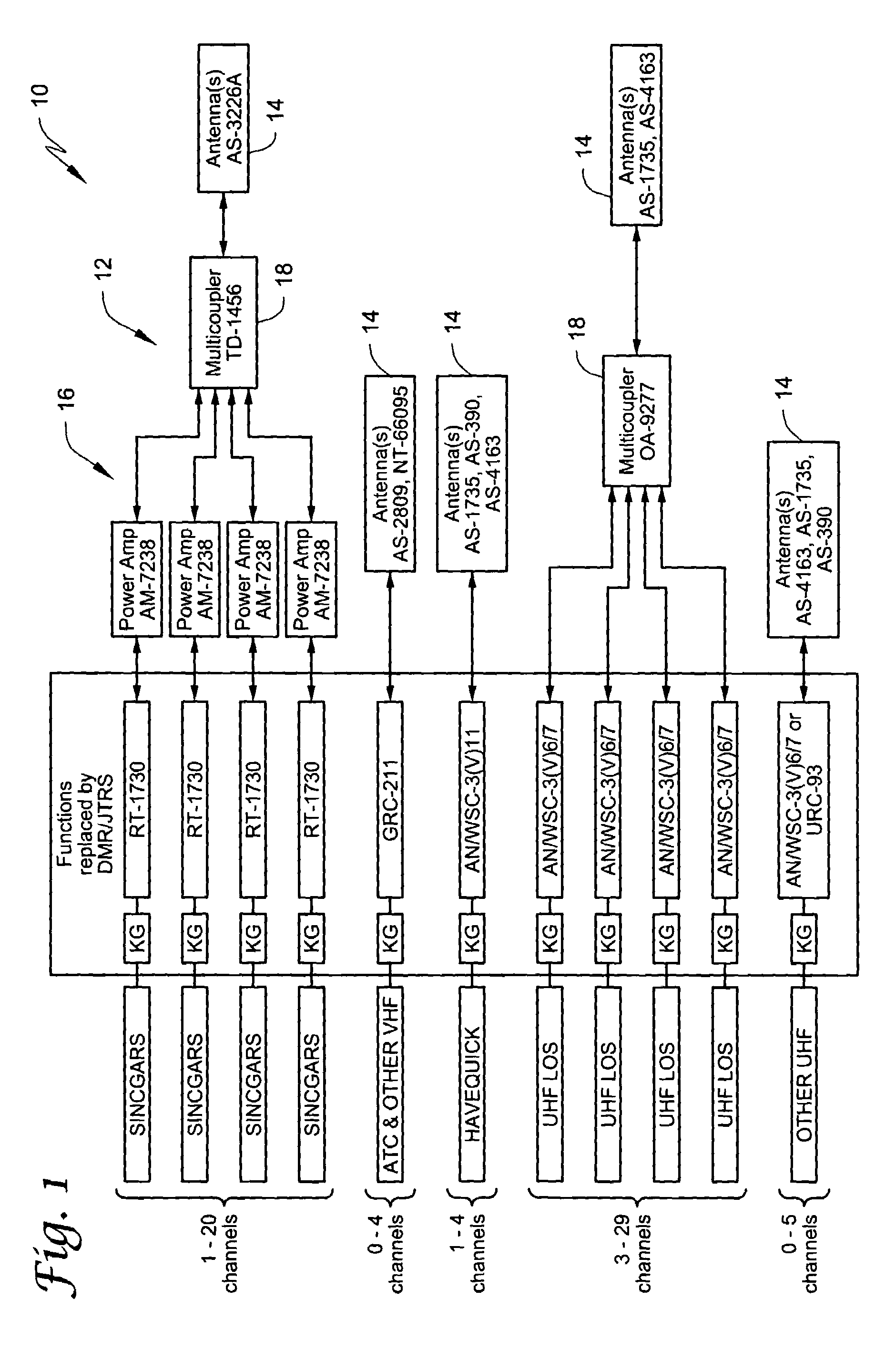
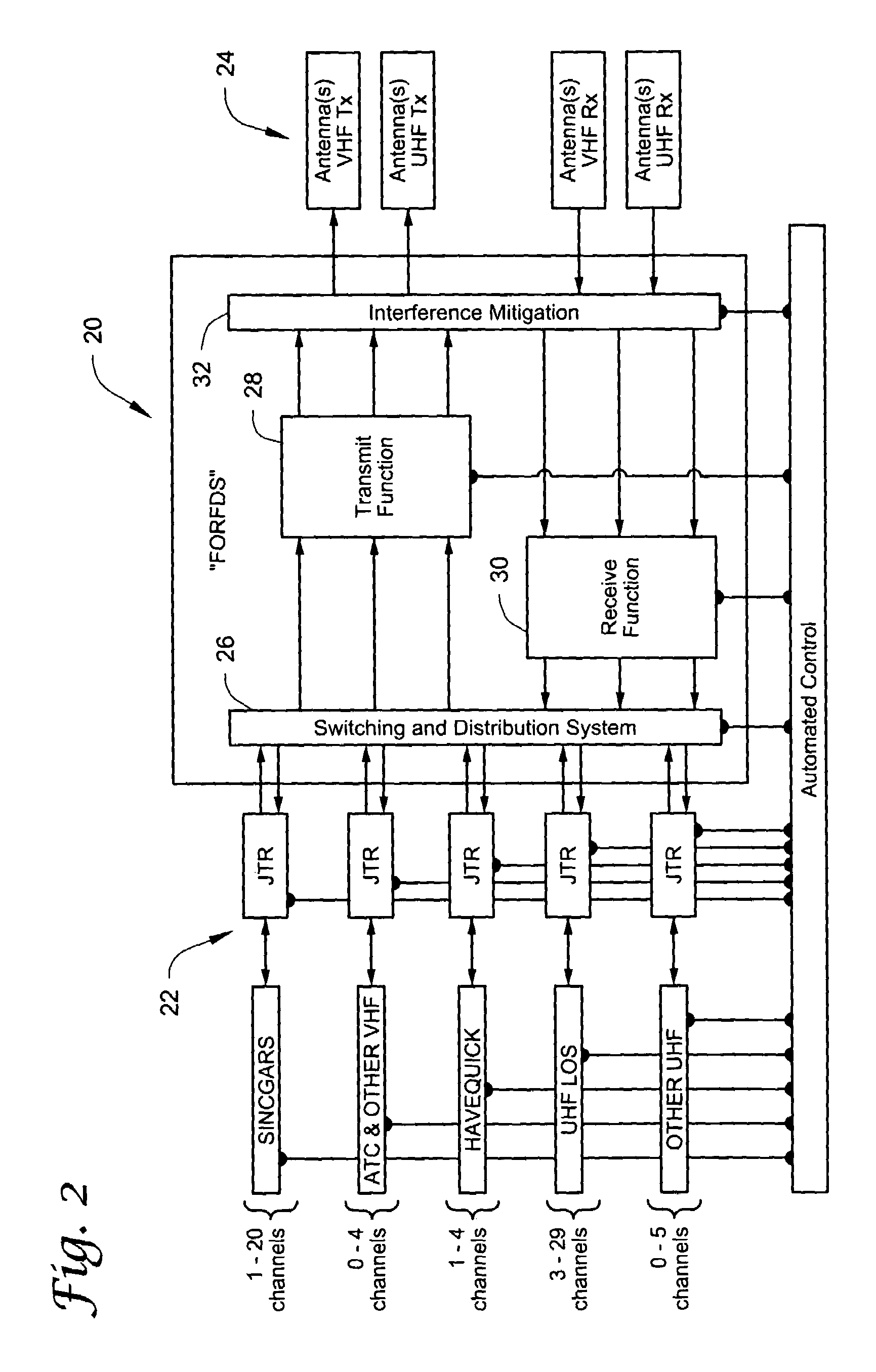
[0024]The one-for-one, or stovepiped connection schemes employed in RF distribution systems associated with shipboard and fixed-site applications are becoming more problematic as communication systems migrate toward a Network Centric architecture [including Joint Tactical Radio System (JTRS) / digital mode radio (DMR) radio systems]. A need therefore exists, as stated herein before, for an RF communication system architecture that is capable of connecting any onboard radio to any onboard antenna while simultaneously eliminating the need for metallic or coaxial type interconnections. The communication system architecture most preferably is also scalable, flexible and automated, such that it can accommodate known communication technologies such as single function Legacy radios, while also being easily adaptable to meet the changing needs required by Network Centric operations, such as, for example, wideband networking waveforms (WNW).

[0025]In view of the foregoing, FIG. 1 depicts a bloc...


PUM


Abstract

A scalable, flexible, automated radio frequency distribution system (FORFDS) employs fiber optics to eliminate the need for metallic / coaxial type interconnections between onboard and fixed-site radios and antennas. Key elements of the FORFDS may include, for example, 1) electrical to optical conversion (and vice versa) of RF signals, 2) optical switching, 3) automated control and monitoring, including Ethernet interfaces, and 4) high density packaging. The system is compatible with JTRS (2 MHz to 2000 MHz), is scalable and cost effective (no longer in the laboratory or concept high cost ranges), compared with known technologies.

Description

BACKGROUND OF THE INVENTION[0001]1. Field of the Invention[0002]This invention relates generally to the field of shipboard communication systems. More particularly, the invention relates to a scalable, flexible, automated fiber optic radio frequency distribution system (FORFDS) that eliminates the need for metallic / coaxial type interconnections between radios and antennas employed onboard ships and at fixed-site installations.[0003]2. Description of the Prior Art[0004]Modern shipboard communication technology typically employs metallic / coaxial cabling to interconnect onboard radios with onboard antennas. Generally, such interconnections use a one-for-one connection scheme or alternatively, a stovepiped connection scheme. Although, a need still exists for conventional radio / antenna connection schemes, such connection schemes are disadvantageous in that they do not allow for flexibility of the onboard radio frequency (RF) systems. In fact, the one-for-one, or stovepiped connection sch...

Claims


Application Information

Patent Timeline
IPC IPC(8): H04B10/00H04B1/38
CPCH04B10/25758
Inventor HOKE, TERRY L.POBIEL, JOSEPH
Owner LOCKHEED MARTIN CORP
Learn More