Varistor and light-emitting apparatus

a varistor and light-emitting technology, applied in the direction of resistor details, overvoltage protection resistors, emergency protective arrangements for limiting excess voltage/current, etc., can solve the problem of affecting the operation of the varistor, the bonding strength between the resistors may be so weak, and the heat transmitted from the metal to the varistor cannot be efficiently dissipated. , to achieve the effect of efficiently diffusing the generated hea

Inactive Publication Date: 2010-04-27
TDK CORPARATION
View PDF10 Cites 10 Cited by
  • Summary
  • Abstract
  • Description
  • Claims
  • Application Information

AI Technical Summary

Benefits of technology

[0005]Meanwhile, varistors can protect electronic devices such as semiconductor light-emitting devices and FET (Field Effect Transistor) against ESD (Electrostatic Discharge) surges when connected in parallel to the electronic devices. The electronic devices include those which generate heat during their operation. When the electronic devices attain a high temperature, they deteriorate their own characteristics, thereby affecting their operation. This makes it necessary to diffuse the generated heat efficiently.
[0006]Therefore, it is an object of the present invention to provide a varistor and a light-emitting apparatus which can efficiently diffuse heat.
[0009]In the varistor in accordance with the present invention, the buffer portion is bonded to each of the metal portion and varistor portion, whereby the buffer portion and metal portion can be bonded firmly to each other, while the buffer portion and varistor portion can be bonded firmly to each other. Therefore, the metal portion and varistor portion can be joined firmly to each other. Hence, the heat transmitted to the varistor can efficiently be diffused from the metal portion.
[0013]Preferably, a bonding surface of the metal portion with the buffer portion is a rough surface. In this case, the bonding strength between the metal portion and buffer portion is enhanced by an anchor effect. This can also alleviate a stress generated by the difference between the coefficient of expansion of the metal portion and that of the buffer portion at the time of heating.
[0015]In the light-emitting apparatus in accordance with the present invention, the two electrode portions of the varistor are connected physically to the semiconductor light-emitting device, whereby the heat generated in the semiconductor light-emitting device is transmitted to the varistor through the two electrode portions. In the varistor, the buffer portion is bonded to each of the metal portion and buffer portion, whereby the buffer portion and metal portion can be bonded firmly to each other, while the buffer portion and the varistor portion can be bonded firmly to each other. Therefore, the metal portion and the varistor portion can be joined firmly to each other. Hence, the heat transmitted to the varistor can efficiently be diffused from the metal portion.
[0016]The present invention can provide a varistor and a light-emitting apparatus which can efficiently diffuse the heat can be provided.

Problems solved by technology

When the electronic devices attain a high temperature, they deteriorate their own characteristics, thereby affecting their operation.
However, when the metal and one outer face of the varistor element body are bonded to each other, the bonding strength therebetween may be so weak that the varistor element body and the metal peel off from each other.
In this case, the heat transmitted from the metal to the varistor cannot be dissipated efficiently.

Method used


Image

  • Varistor and light-emitting apparatus
  • Varistor and light-emitting apparatus
  • Varistor and light-emitting apparatus

Examples


first embodiment

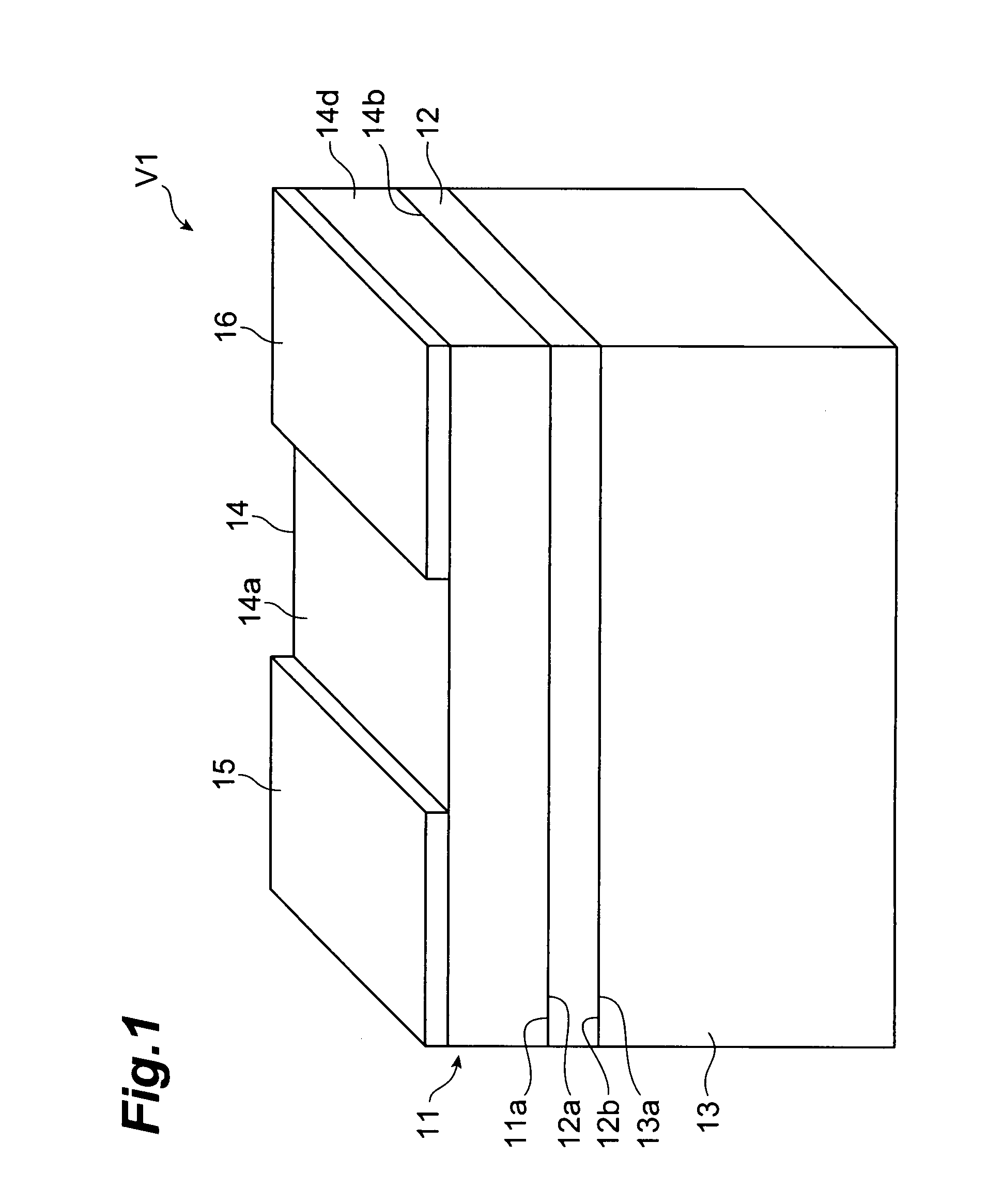
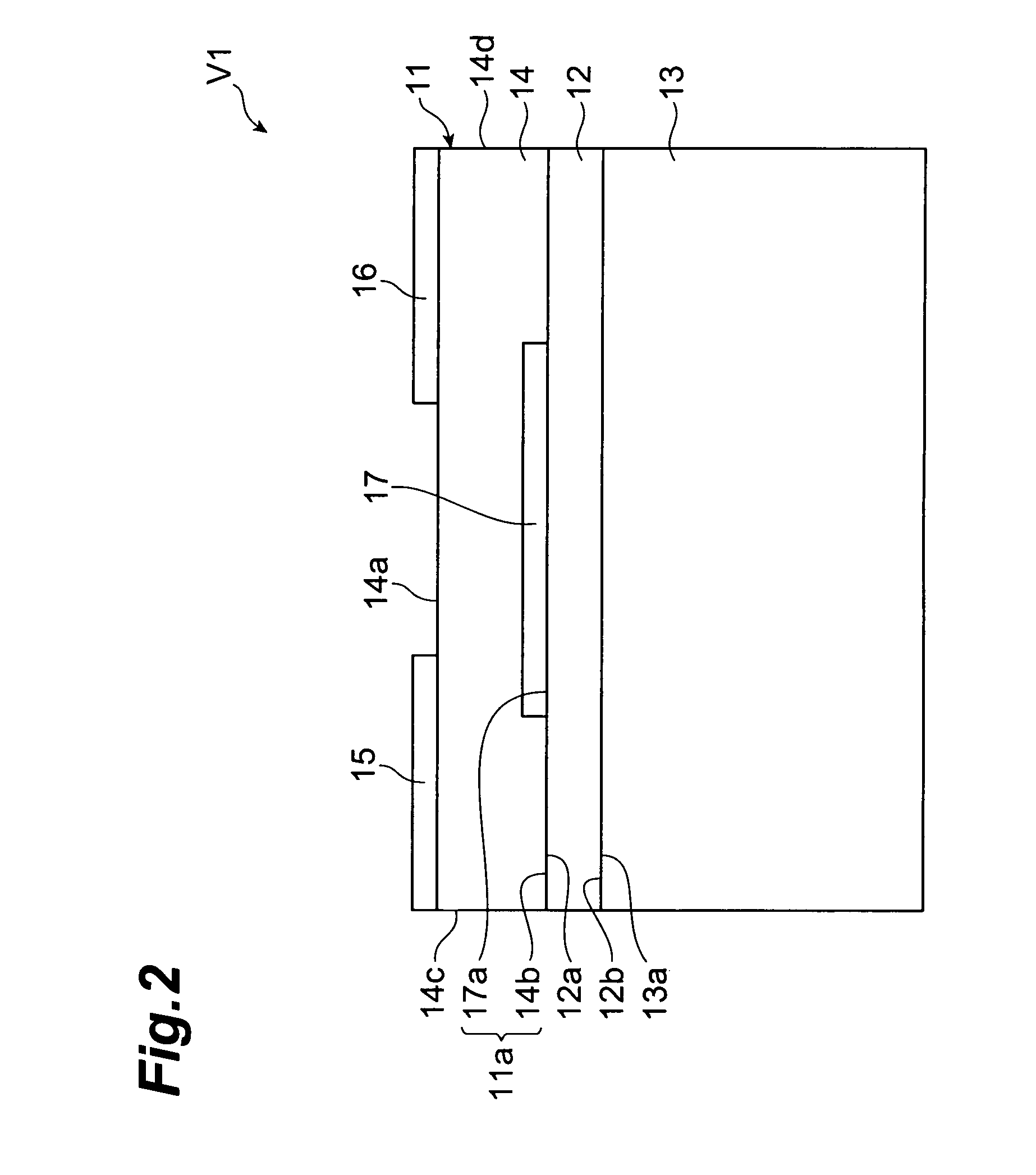
[0027]The configuration of a varistor V1 in accordance with a first embodiment will be explained with reference to FIGS. 1 and 2. FIG. 1 is a schematic perspective view showing the varistor in accordance with the first embodiment. FIG. 2 is a schematic sectional view showing the varistor in accordance with the first embodiment. The varistor V1 has a substantially rectangular parallelepiped form and comprises a varistor portion 11, a buffer portion 12, and a metal portion 13. Each of the varistor portion 11 and metal portion 13 has a substantially rectangular parallelepiped form. The buffer portion 12 has principal faces 12a, 12b opposing each other. The principal face 12a is bonded to one face of the varistor portion 11, whereas the principal face 12b is bonded to one face of the metal portion 13.

[0028]The varistor portion 11 comprises a varistor element body 14, a first electrode portion 15, a second electrode portion 16, and a third electrode portion 17.

[0029]The varistor element ...

second embodiment

[0059]With reference to FIG. 3, the configuration of a varistor V2 in accordance with a second embodiment will be explained. FIG. 3 is a schematic sectional view showing the varistor in accordance with the second embodiment. The configuration of the varistor V2 will be explained mainly in terms of differences from the configuration of the varistor V1 mentioned above. The varistor V2 comprises a varistor portion 21 and the above-mentioned buffer portion 12 and metal portion 13. The varistor portion 21 comprises a varistor element body 14, a first electrode portion 15, and a second electrode portion 16. Namely, the varistors V1 and V2 differ from each other in that the varistor V2 is not equipped with the third electrode portion 17. In the varistor portion 21, as mentioned above, the first electrode portion 15 and second electrode portion 16 function as I / O terminals of the varistor V2, while the varistor element body 14 functions as a region exhibiting a nonlinear current-voltage cha...

third embodiment

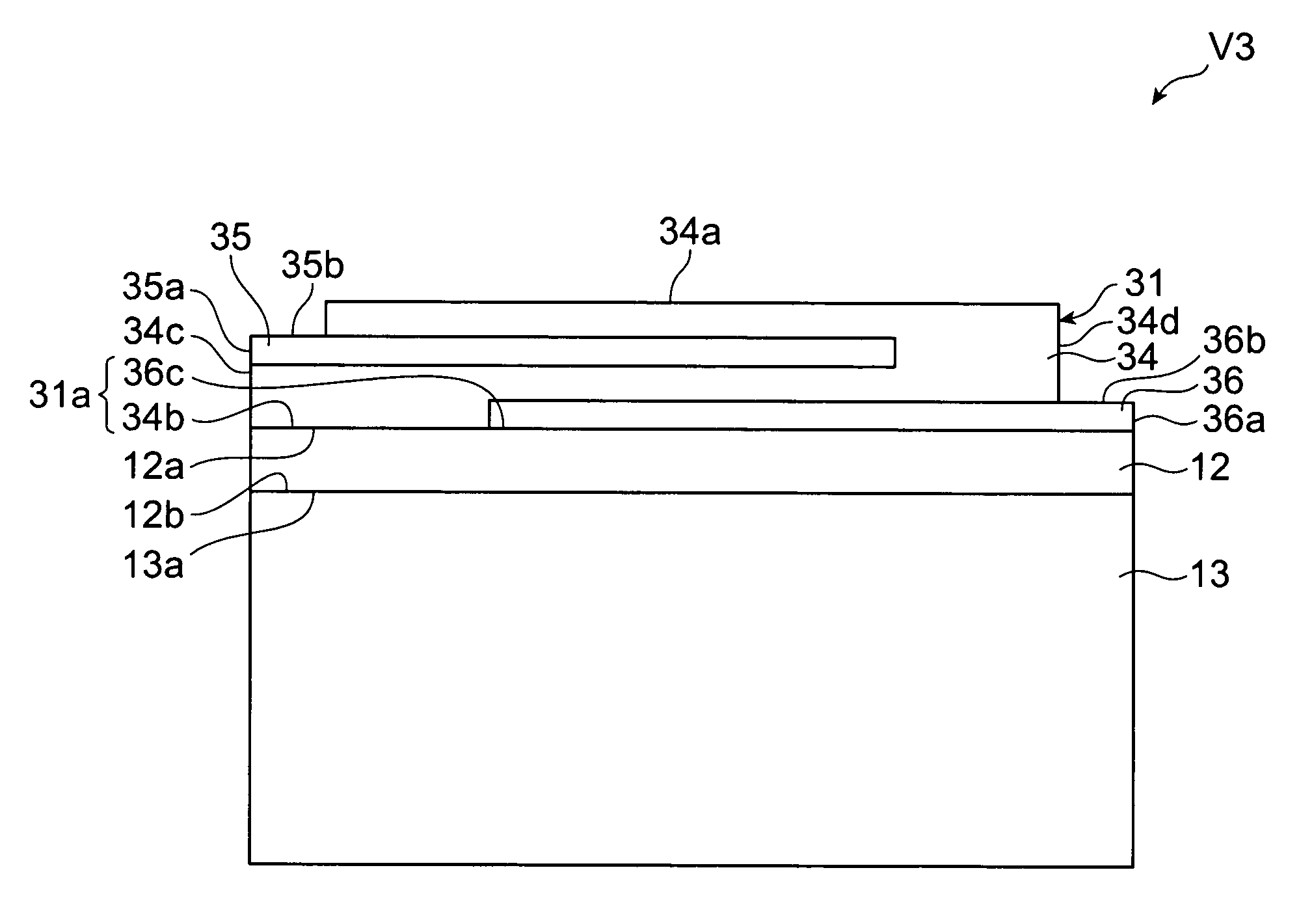
[0061]With reference to FIG. 4, the configuration of a varistor V3 in accordance with a third embodiment will be explained. FIG. 4 is a schematic sectional view showing the varistor in accordance with the third embodiment. The configuration of the varistor V3 will be explained mainly in terms of differences from the configuration of the varistor V1 mentioned above. The varistor V3 comprises a varistor portion 31 having a configuration different from that of the varistor portion 11 and the above-mentioned buffer portion 12 and metal portion 13. The varistor portion 31 has a substantially rectangular parallelepiped form comprising a varistor element body 34, a first electrode portion 35, and a second electrode portion 36.

[0062]The varistor element body 34 is formed into a substantially rectangular parallelepiped shape having faces 34a, 34b opposing each other, side faces 34c, 34d which are perpendicular to the faces 34a, 34b and oppose each other, and two side faces which are adjacent...


PUM


Abstract

A varistor comprises a varistor portion, a metal portion, and buffer portion. The varistor portion has a varistor element body exhibiting a nonlinear current-voltage characteristic and two electrode portions. The metal portion has a thermal conductivity higher than that of the varistor element body. The buffer portion is disposed between the varistor portion and metal portion so as to be bonded to each of the varistor portion and metal portion and mainly composed of glass. The two electrode portions are arranged in the varistor element body so as to be electrically insulated from each other while exposing at least a portion of each thereof from an outer surface of the varistor element body. The metal portion and varistor portion are joined firmly to each other. The heat transmitted to the varistor can efficiently be diffused from the metal portion.

Description

BACKGROUND OF THE INVENTION[0001]1. Field of the Invention[0002]The present invention relates to a varistor and a light-emitting apparatus comprising the varistor.[0003]2. Related Background Art[0004]Known as a varistor is one comprising a element body having a varistor element body exhibiting a nonlinear current-voltage characteristic and a pair of internal electrodes disposed so as to interpose a portion of the varistor element body between them, and a pair of terminal electrodes formed on an outer surface of the element body and respectively connected to their corresponding internal electrodes (see, for example, Japanese Patent Application Laid-Open No. 2002-246207).SUMMARY OF THE INVENTION[0005]Meanwhile, varistors can protect electronic devices such as semiconductor light-emitting devices and FET (Field Effect Transistor) against ESD (Electrostatic Discharge) surges when connected in parallel to the electronic devices. The electronic devices include those which generate heat du...

Claims


Application Information

Patent Timeline
Patent Type & Authority Patents(United States)
IPC IPC(8): H01C7/10H01L33/12H01L33/32H01L33/62
CPCH01C7/102H01C7/1006H01C1/142H01L2224/16225H01L2224/05573H01L2224/05568H01L24/05
Inventor SAITO, YOSATO, HIROYUKITANAKA, HITOSHINUMATA, MAKOTOTAKEUCHI, GORO
Owner TDK CORPARATION
Why Eureka
Try Eureka