Crosslinked polysaccharide sponge

a polysaccharide sponge and crosslinked technology, applied in the field of polysaccharide sponges, can solve the problems of difficult washing of porous materials such as sponges, easy decomposition in vivo,

Inactive Publication Date: 2010-04-20
SEIKAGAKU KOGYO CO LTD
View PDF26 Cites 2 Cited by
  • Summary
  • Abstract
  • Description
  • Claims
  • Application Information

AI Technical Summary

Benefits of technology

[0012]The present invention has been attained to solve the above problems. An object of the present invention is to provide a polysaccharide sponge from which impurities can be easily removed.
[0022]Examples of the photoreactive residues may include cinnamic acid, substituted cinnamic acids such as aminocinnamic acid (i.e., cinnamic acid derivative obtained by substituting any of hydrogen atoms bonded to the benzene ring with amino group, preferably p-aminocinnamic acid), acrylic acid, maleic acid, fumaric acid, furyl acrylic acid, thiophene acrylic acid, cinnamylidene acetate, sorbic acid, thymine, cumarin or the like. Of these photoreactive residues, preferred are those having a vinylene group capable of forming a cyclobutane ring by irradiating light thereto, and more preferred are cinnamic acid and substituted cinnamic acids, especially aminocinnamic acid, in the consideration of good photoreactivity and high safety to living organism. Also, in order to minimize adverse influence of the photoreactive residue on the polysaccharide, the photoreactive residue is preferably bonded to the polysaccharide through a spacer. Therefore, most preferred photo-crosslinking groups are derivatives of cinnamic acid or substituted cinnamic acids to which the spacer is bonded.
[0031]In the present invention, undesirable substances other than the photoreactive polysaccharide, solvent and organic acid salts in the buffer solution, which should be prevented from remaining in the finally obtained polysaccharide sponge, for example, reaction reagents containing unreacted photo-crosslinking group, impurities and foreign materials, are previously removed from the solution to enhance a purity of the obtained polysaccharide sponge to such an extent that the sponge can be used in medical applications, e.g., as medical equipment. The removal of impurities and foreign materials from the solution can be performed by known methods such as dialysis, filtration and centrifugal separation. The photoreactive polysaccharide is usually soluble in a mixed solution of water and a water-soluble organic solvent and, therefore, can be dissolved therein to form a polysaccharide solution. Accordingly, when the polysaccharide solution is subjected to removal procedure for impurities and foreign materials, it is possible to more easily remove residual reaction regents that are unreacted with the polysaccharide from the solution. In particular, up-on production of a porous sponge that is not readily washable, it is especially useful to obtain a high-purity photoreactive polysaccharide as the raw material.
[0035]Also, the light irradiation time may be appropriately varied according to an output power of the light source and aimed applications of the photo-crosslinked polysaccharide. For example, when cinnamic acid is used as the photo-crosslinking group and when 10 ml of the photoreactive polysaccharide solution is irradiated by one 400 W high-pressure mercury lamp to produce a crosslinked polysaccharide sponge, the light irradiation is performed as follows. That is, in order to obtain a polysaccharide sponge having a relatively high mechanical strength (usually not less than 350 g when using a 4-wt. % photoreactive polysaccharide solution and not less than 100 g when using a 2-wt. % photoreactive polysaccharide solution as measured by the method defined in the below-mentioned Examples), the polysaccharide solution is placed 4 cm apart from the light source, and irradiated with light at an intensity of 10.9 to 11.3 mW / cm2 (calculated as 280 nm ultraviolet light) for a period of from 30 seconds to 7 minutes. In the case where the solution is irradiated with light for a longer period, it is possible to obtain a polysaccharide sponge having a still higher hardness. In addition, even though the irradiation time is the same, when the light source with a lower output and the longer distance from the light source are used, it becomes possible to obtain a polysaccharide sponge having a lower crosslinking degree and, therefore, a more excellent biodegradability.

Problems solved by technology

However, many polysaccharides having such a good biocompatibility have a hydrophilicity and, therefore, tend to be easily decomposed in vivo.
However, in the above-mentioned method, since the obtained sponge still contains the unreacted crosslinking agent, it is required to subject the sponge to post-washing treatment.
However, it may be extremely difficult to wash a porous material such as sponges.

Method used


Image

  • Crosslinked polysaccharide sponge
  • Crosslinked polysaccharide sponge
  • Crosslinked polysaccharide sponge

Examples


example 1

[0046]1 g of photoreactive hyaluronic acid obtained by introducing aminopropyl cinnamate into 3% of whole carboxyl groups of hyaluronic acid (produced by Seikagaku Kogyo Corporation; weight-average molecular weight: 900,000) (introduction percentage: 3%) was dissolved in 25 ml of injection water to prepare a 4 wt. % photoreactive hyaluronic acid solution. The thus obtained aqueous solution was interposed between two hard (Pyrex) glass plates (produced by Asahi Technoglass Co., Ltd.) so as to form a layer of the solution with a thickness of 1 mm, and then rapidly frozen under an atmosphere of −80° C. While keeping the frozen state, the frozen solution was irradiated with light for 5 minutes using a high-pressure mercury lamp (400 W lamp manufactured by Shigemi Standard Co., Ltd.). After the irradiation, the obtained material was thawed at room temperature to obtain a white photo-crosslinked hyaluronic acid sponge.

[0047]As a result of visually observing the thus obtained photo-crossli...

example 2

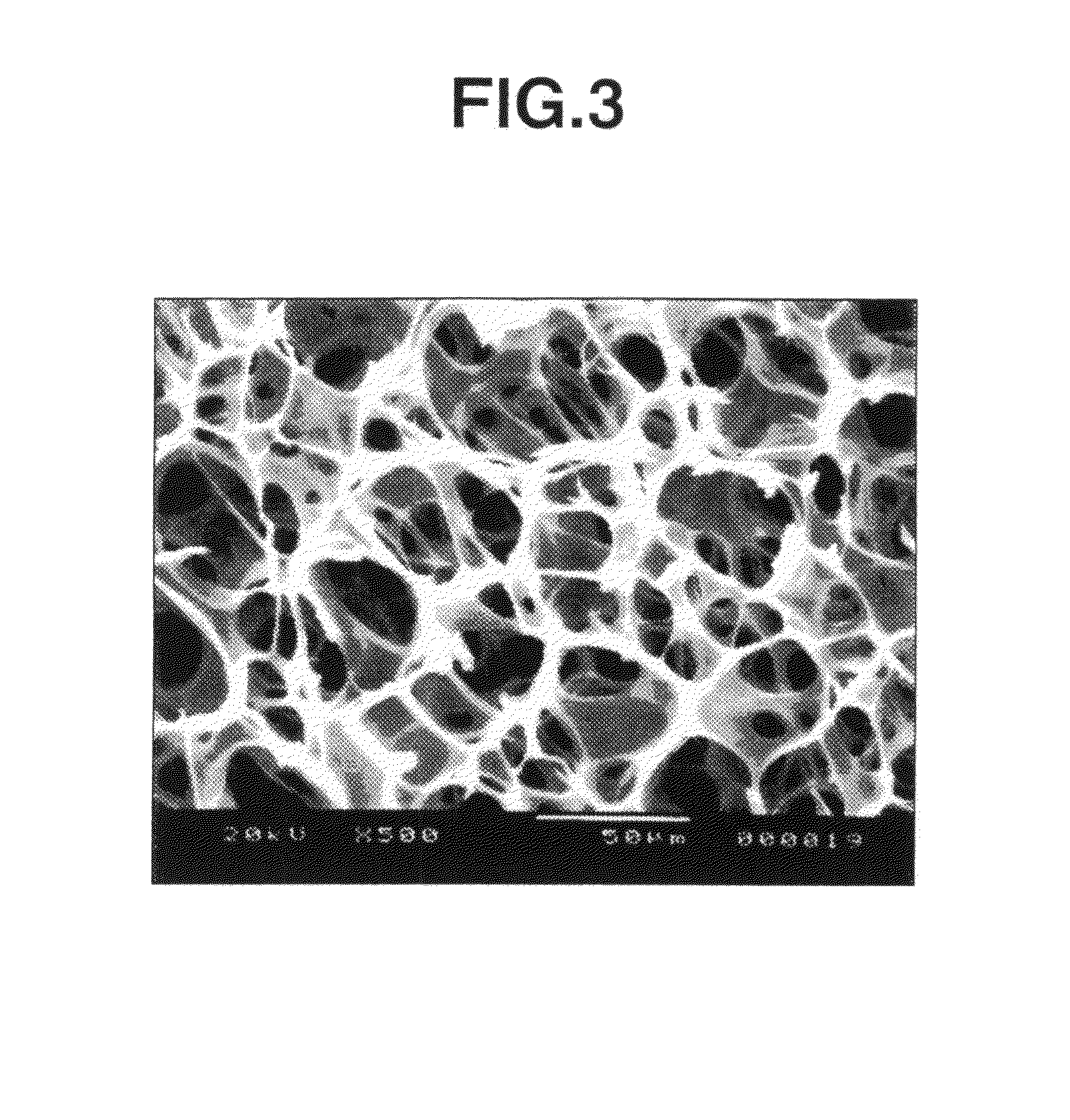
[0049]The frozen photoreactive hyaluronic acid solution produced by the same method as defined in Example 1 was irradiated with light for 7 minutes to obtain a photo-crosslinked hyaluronic acid sponge. The thus obtained photo-crosslinked hyaluronic acid sponge was a porous material and exhibited excellent water absorbing and discharging properties similarly to the sponge obtained in Example 1.

[0050]The section of the thus obtained photo-crosslinked hyaluronic acid sponge was observed by an electron microscope (scanning electron microscope “JSM-5200”). As a result, it was confirmed that the sponge had 92 pores per a photographed area (160×246 μm=39,360 μm2), and the 56 pores thereof (61%) had a pore diameter of 10 to 50 μm (FIG. 3).

example 3

[0051]1 g of photoreactive hyaluronic acid obtained by introducing aminopropyl cinnamate into 3% of whole carboxyl groups of hyaluronic acid (produced by Seikagaku Kogyo Corporation; weight-average molecular weight: 900,000) (introduction percentage: 3%) was dissolved in 25 ml of injection water to prepare a 4 wt. % photoreactive hyaluronic acid solution. The thus obtained aqueous solution was interposed between two hard (Pyrex) glass plates (produced by Asahi Technoglass Co., Ltd.) so as to form a layer of the solution with a thickness of 1 mm. Then, the solution was rapidly frozen under an atmosphere of −80° C., and freeze-dried in vacuo at 20° C. under a pressure of 10 mmHg for 24 hours, thereby obtaining a photoreactive hyaluronic acid sponge (freeze-dried product). The thus obtained freeze-dried product was irradiated with light at ordinary temperature for 5 minutes using a high-pressure mercury lamp (400 W lamp manufactured by Shigemi Standard Co., Ltd.) to obtain a photo-cros...


PUM

PropertyMeasurementUnit
pore diameteraaaaaaaaaa
water contentaaaaaaaaaa

Abstract

A process for producing a polysaccharide sponge comprises the steps of (A) freezing a photoreactive polysaccharide solution, and (B) irradiating the frozen photoreactive polysaccharide solution with light to crosslink the photoreactive polysaccharide, thereby obtaining the polysaccharide sponge. The process includes simplified steps requiring no removal of solvent, and has such an advantage that impurities are easily removed therefrom.

Description

[0001]This application is a continuation of application Ser. No. 10 / 470,349 filed Oct. 15, 2003, which in turn is the U.S. national phase of international application PCT / JP02 / 00720 filed 30 Jan. 2002, which designated the U.S., which claims priority of Japanese application 2001-24159 filed Jan. 31, 2001.TECHNICAL FIELD[0002]The present invention relates to a polysaccharide sponge and a process for producing the same. The “sponge” used herein means a porous material having closed cells or open or interconnected cells.BACKGROUND ART[0003]Various attempts have been performed for applying polymeric sponges to living organism because of a good water absorption property thereof. Among them, sponges made of biodegradable polysaccharide are useful owing to a high affinity to the living organism, i.e., a good biocompatibility. However, many polysaccharides having such a good biocompatibility have a hydrophilicity and, therefore, tend to be easily decomposed in vivo. For this reason, polysac...

Claims


Application Information

Patent Timeline
Patent Type & Authority Patents(United States)
IPC IPC(8): C07H5/06A61K31/728C07H5/04C08B11/12C08B11/20C08B15/00C08B37/00C08B37/04C08B37/08C08B37/10C08F299/00C08J9/28C08J9/36C08L5/00
CPCC08B11/12C08B15/005C08B37/00C08B37/003C08B37/0069C08B37/0072C08B37/0075C08B37/0084C08F28/06C08F251/00C08F251/02C08J9/28C08L5/00C08L51/02C08B11/20Y10T428/249953C08J2201/0484C08J2305/00
Inventor SATO, TOMOYA
Owner SEIKAGAKU KOGYO CO LTD
Why Eureka
Try Eureka