
Assembly of an electrodynamic fractionating unit

a technology of electrodynamic fractionation and assembly, which is applied in the direction of grain treatment, etc., can solve the problems of not being very effective, generating shock waves, and no longer having energy for actual fractionation operation, and achieves the effect of being easy to handl

Active Publication Date: 2010-03-16
KERNFORSCHUNGSZENTRUM KARLSRUHE GMBH
View PDF10 Cites 10 Cited by
  • Summary
  • Abstract
  • Description
  • Claims
  • Application Information

AI Technical Summary

Benefits of technology

[0012]The energy store together with its output switch, wherein the latter is normally a spark gap primarily operated or triggered by self disruptive discharge, the electrodes together with the feed line, and the reaction vessel are positioned in a volume that is completely enclosed by an electrically conductive wall, meaning the encapsulation, while maintaining the required insulation distance to areas with different electrical potential. The volume between the encapsulation and therein disposed components is kept at a minimum and the inductivity of the unit is consequently restricted to the unavoidable minimum. Applying the laws of electro-physics in this manner makes it possible to achieve the shortest rise time for the discharge pulse, typical for a unit of this type.
[0020]According to an embodiment, the electrode at reference potential is consequently positioned in the center of the front wall of the reaction vessel while the high-voltage electrode is positioned at a distance thereto in the center of the opposite wall (claim 6). The high-voltage electrode is connected directly to the output switch of the energy store, wherein this output switch is the output spark gap when a Marx generator is used for the energy store. As a result, the electrically most advantageous and the insulation-technically most useful coaxial design is obtained for any type of encapsulation, thus making it possible to satisfy the requirements of encapsulation and the lowest inductivity, typical for these units.
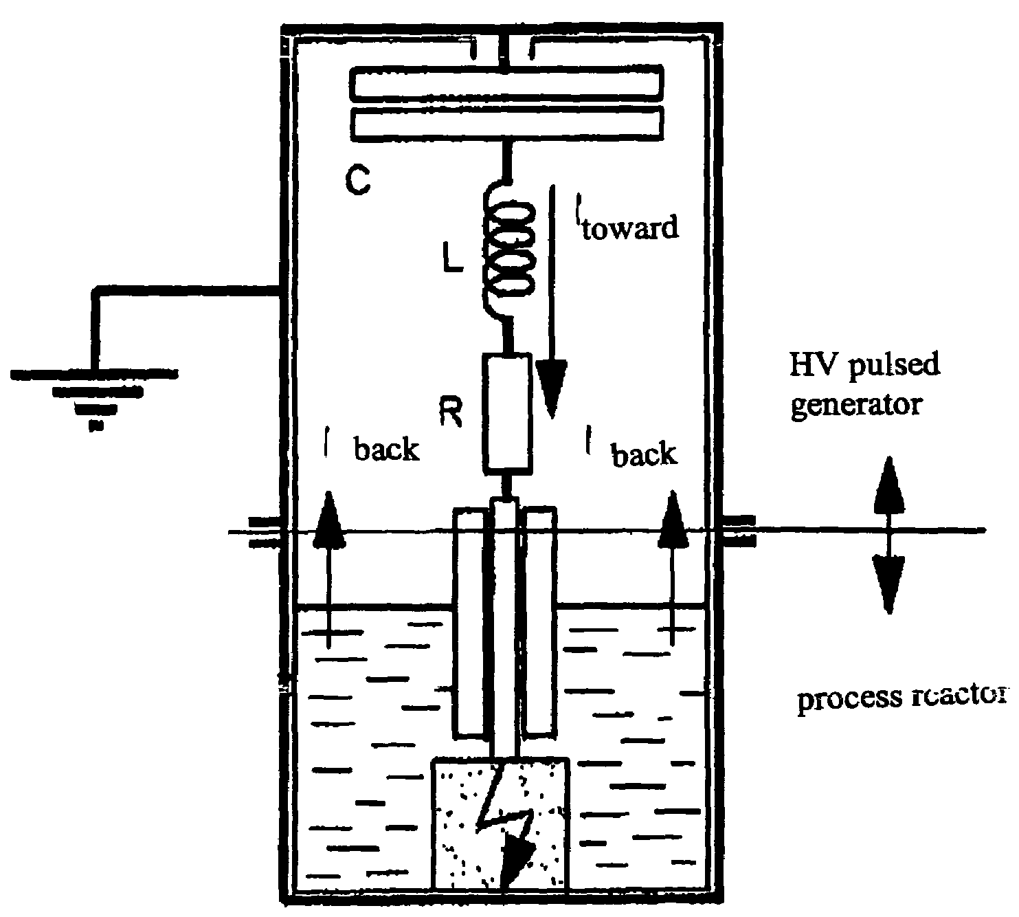
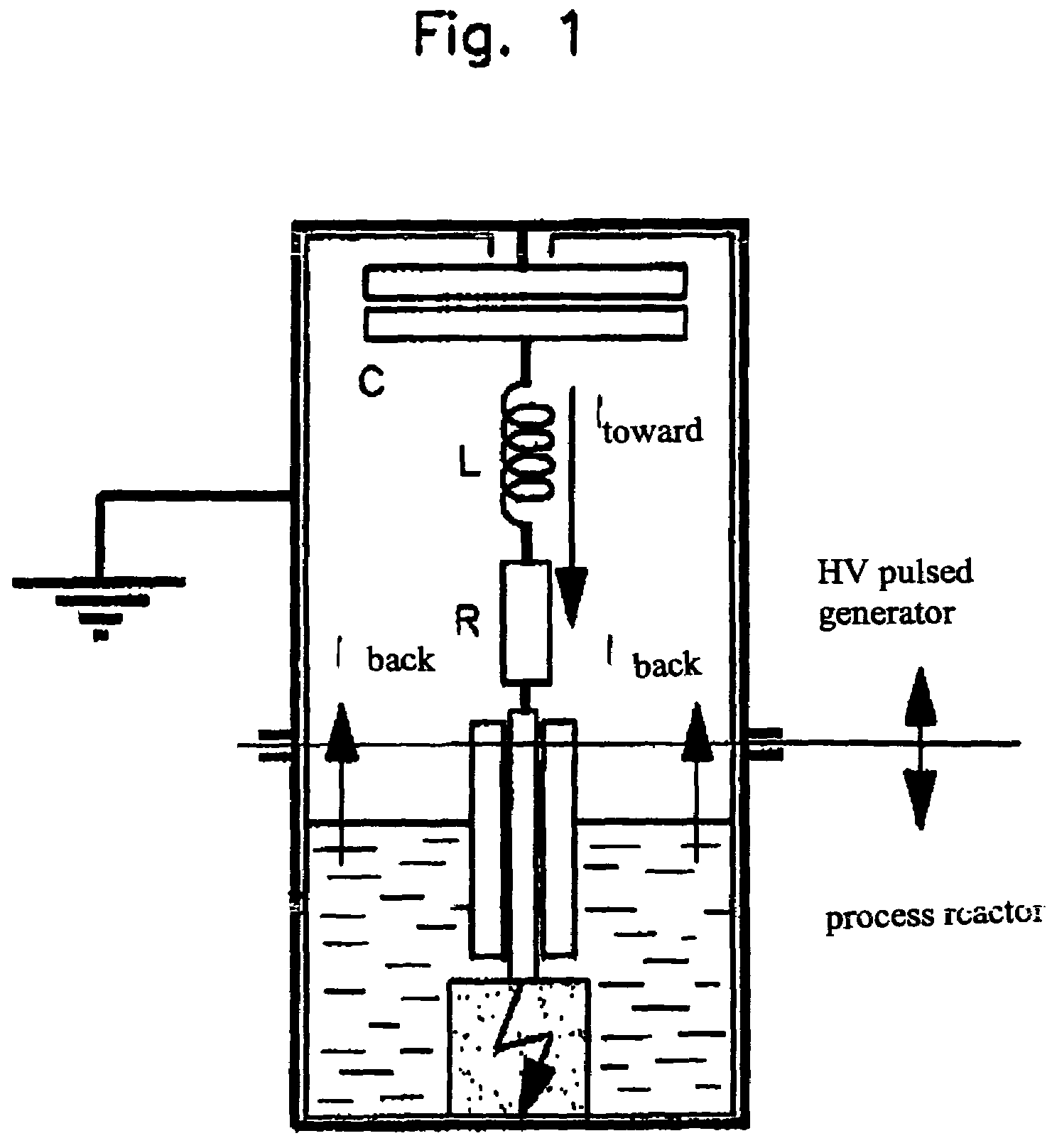
[0028]The minimum inductivity and the minimum ohmic resistance of the pulse circuit result in a more efficient discharge into the load, meaning to a higher amount of energy being introduced into the load. The so-to-speak closed design of the unit has critical advantages with respect to the electromagnetic radiation and the protection against contact. The discharge current flows exclusively on the inside of the unit during the complete duration of the HV pulse interval. In any case, this is self-evident since the current flows from the energy store comprising the pulse generator, via the high-voltage electrode and the load, the reaction fluid with fragmentation product, to the bottom of the reaction vessel because of the screening function of the electrically conductive encapsulation.
[0030]The unit with coaxial assembly is compact, easy to handle, and accessible from a measuring and control technical point of view. The electrical charging device for the energy store does not have to be screened separately. Its feed line can extend with the aid of bushings and without problem to the energy store, located in the top inside area of the housing, possibly by means of a coaxial cable with an outside conductor that makes contact with the housing.

Problems solved by technology

An arc-over which travels only through the process fluid at best can only generate shock waves, which are not very effective.
This energy amount consequently is no longer available for the actual fractionating operation.
In turn, this quickly leads to extensive protective installations over and above the actual assembly for use.
The ohmic losses in the high-voltage pulse circuit are also limited to the unavoidable minimum level;
In addition, no electromagnetic radiation can escape to the outside.

Method used


Image

  • Assembly of an electrodynamic fractionating unit
  • Assembly of an electrodynamic fractionating unit
  • Assembly of an electrodynamic fractionating unit

Examples


Embodiment Construction

[0037]FIG. 1 schematically shows a sectional view in axial direction through the coaxially assembled FRANKA unit. The continuous or discontinuous mode of operation is not taken into consideration herein because the emphasis is on the electrical layout. Also not indicated is the electrical charging device for charging the electrical energy store 3. From an electrical point of view, the coaxial assembly is extremely advantageous and a change from this assembly would be made only for compelling structural reasons.

[0038]The high-voltage pulse generator consists of the schematically shown electrical store C in the form of a capacitor, the inductivity L, and the ohmic resistance R, which are connected in series. The high-voltage electrode 5 follows. This electrode is electrically insulated against the environment by a dielectric casing, starting with the electrical connection to the resistance R and extending into the end region. Its exposed end region 4 is submerged in a process / reaction...


PUM


Abstract

The assembly of an electrodynamic fractionating unit, for the fragmentation, milling or suspension of a brittle, mineral process material is disclosed. The energy store including the output switch / spark gap thereof, the electrodes including the supply line and the reaction vessel are each arranged at least within the protection of the electrically necessary insulating separation of regions of differing electrical potential, completely enclosed in a volume of the encapsulation, having electrically-conducting walls. The wall thickness of the encapsulation is at least equivalent to the penetration depth, corresponding to the lowest components of the Fourier spectrum of the pulsed electromagnetic field. The electrode at reference potential is connected to the ground side of the energy store through the encapsulation wall. The electrode at high voltage is connected by the shortest path to the output switch on the energy store.

Description

BACKGROUND[0001]1. Field of the Invention[0002]The invention relates to the assembly of an electrodynamic fractionating unit (FRANKA=Fraktionieranlage Karlsruhe), used for fragmenting, grinding, or suspending a brittle mineral material to be processed.[0003]2. Related Art[0004]All presently known units of this type, developed for the processing of mineral materials by means of fragmenting, material removal, drilling or similar processing methods, in particular the electrodynamic method, with the aid of high-power, high-voltage discharges, comprise the following main components:[0005]The energy store, meaning the unit for generating a high-voltage (HV) pulse, which frequently or in most cases is a Marx generator known from the field of high-voltage pulse technology, and the application-specific reaction / process vessel filled with a process fluid. The exposed end region of a high-voltage electrode which is connected to the energy store is completely submerged into this fluid. The elec...

Claims


Application Information

Patent Timeline
IPC IPC(8): B02C19/00B02C13/286B02C19/18
CPCB02C19/18B02C2019/183
Inventor HOPPE, PETERGIESE, HARALD
Owner KERNFORSCHUNGSZENTRUM KARLSRUHE GMBH
Learn More