
Apparatus and method for door and window head flashing

a technology for flashing and door and window head, applied in the direction of girders, snow traps, joists, etc., can solve the problems of difficulty in ordering and storing many different sizes of flashing units, and the volume of each size would be required to pay for the tool, so as to prevent water intrusion

Active Publication Date: 2010-03-16
TEODOROVICH MISHKO
View PDF23 Cites 37 Cited by
  • Summary
  • Abstract
  • Description
  • Claims
  • Application Information

AI Technical Summary

Benefits of technology

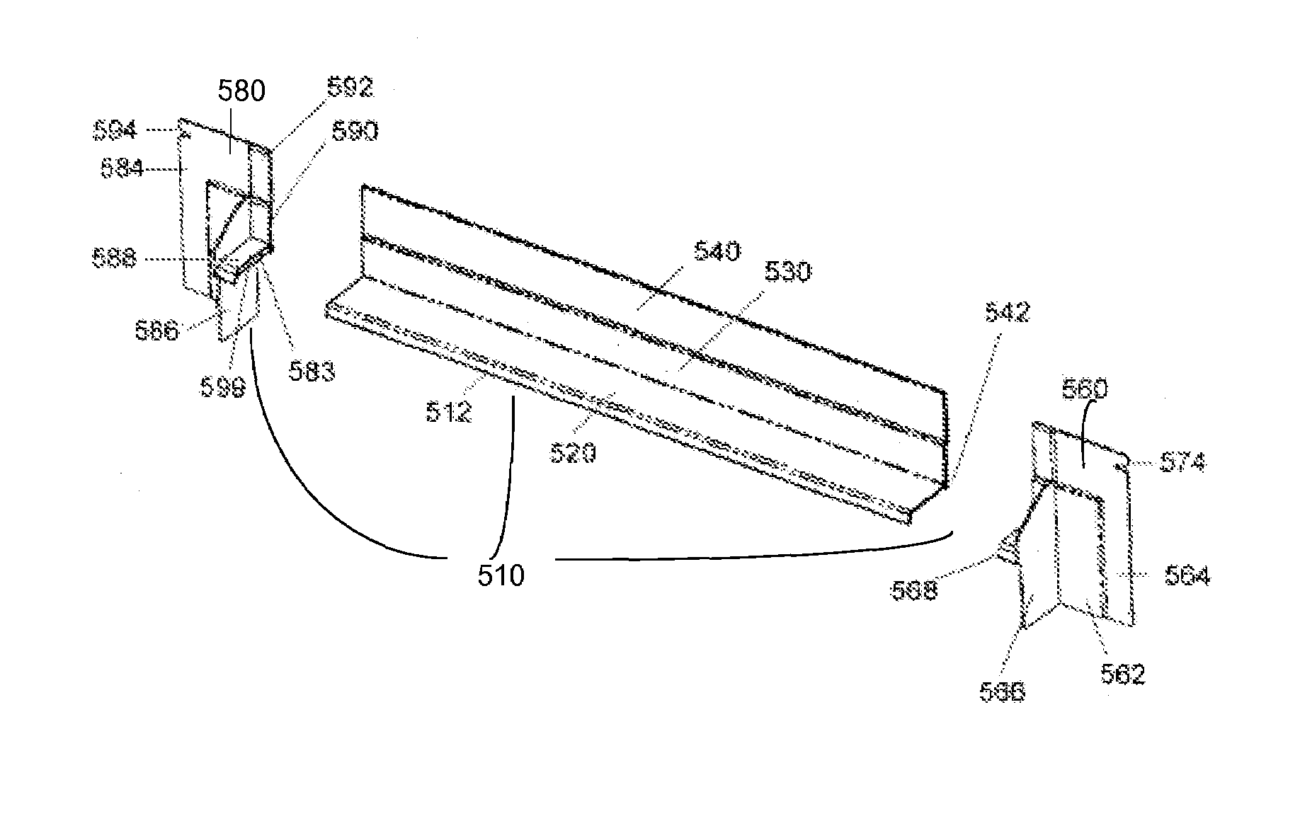
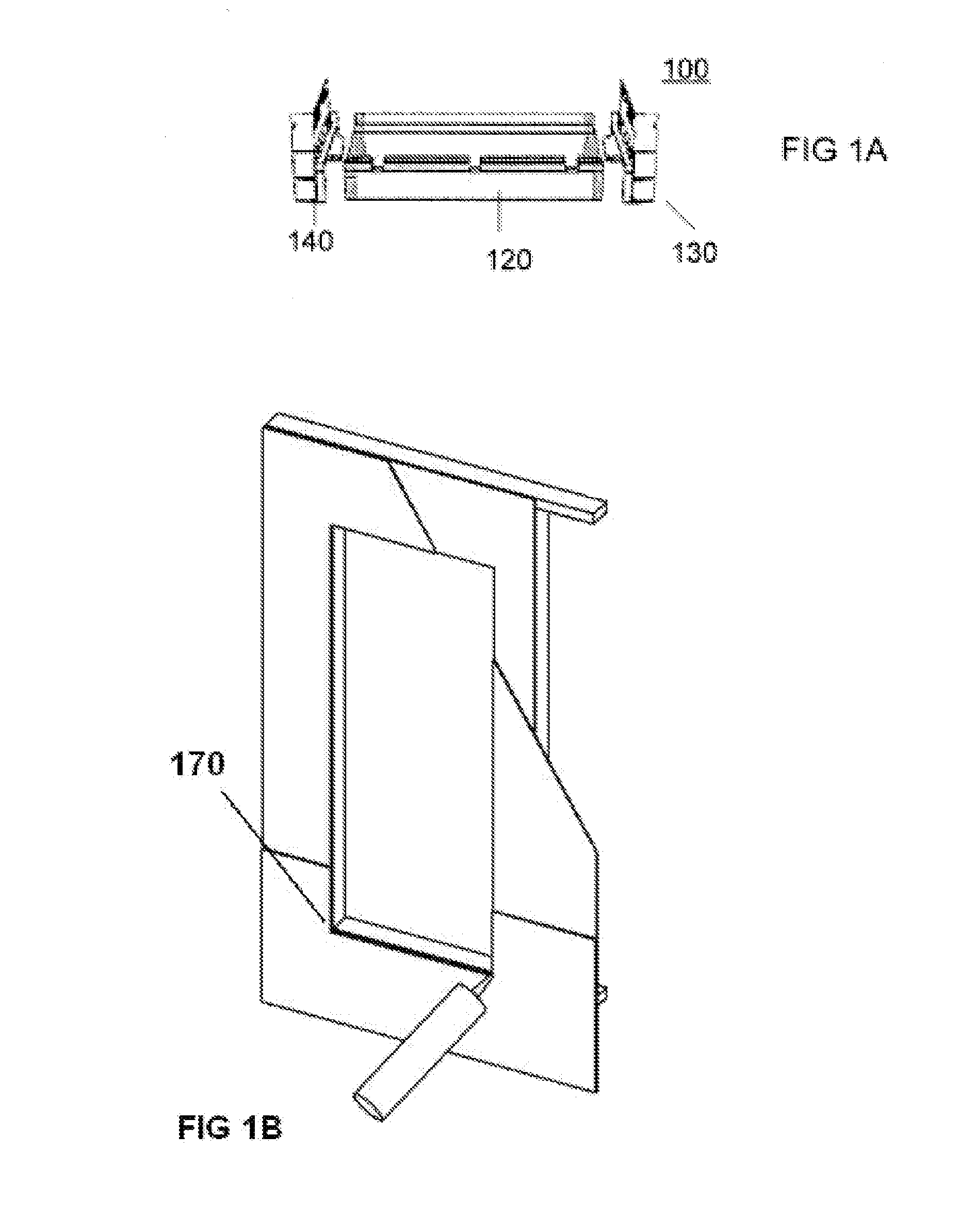
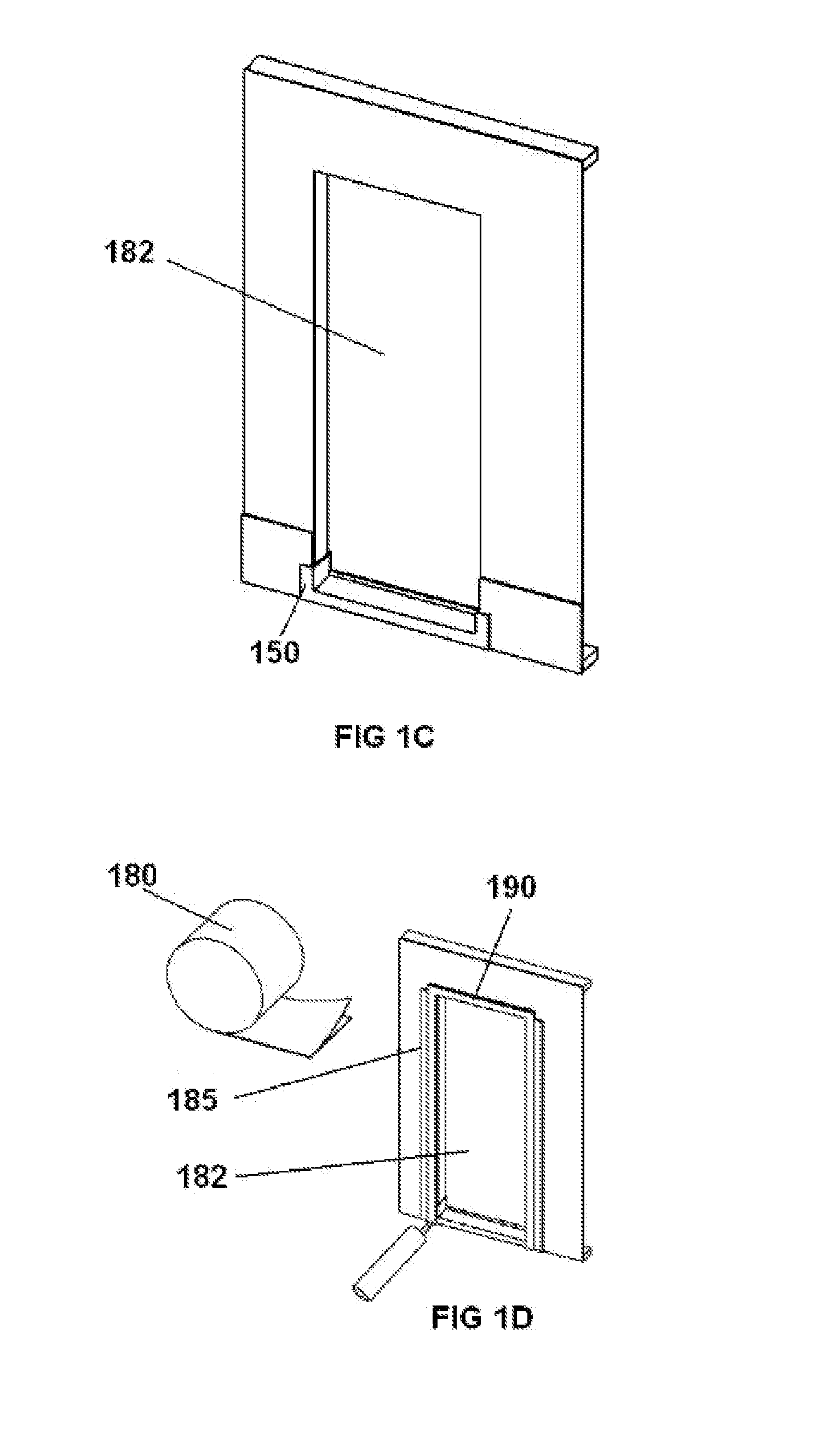
[0009]The current invention is for a window and door head flashing system and method, which used in combination with other devices and methods prevents water intrusion and accumulation around windows and doors. The SureSill HeadFlash™ is designed to discharge water above a window or door to the exterior of the building. In one embodiment, a head flash assembly is constructed from a center section and end caps. During installation, the center section, DrainShield™, is placed over the brick mould or is installed on top of the window or door. The end caps overlap the sides of the window or door. The end caps also prevent water build up above the window or door from going down the sides of the window or door. The center section and end caps may be provided in desired sizes or materials.
[0010]In some embodiments of the current invention, the device can be made in a low cost manufacturing operation by extrusion. In one embodiment, HeadFlash™, a head flashing assembly is made by combining extrusion and injection molding processes. The head flashing assembly typically includes insets to accept window flanges, nailing slots, a front flange, and a back flange. End caps can be snapped or otherwise attached to the base.
[0011]In another embodiment, the head flashing may be formed of a combination of rigid and flexible plastics, so that it can be easily formed over arched windows while retaining a desirable cross-sectional shape.

Problems solved by technology

Also, if an injection molding tool were required for each size, then relatively high volumes of each size would be required to pay for the tool.
It is difficult to order and store many different sizes of flashing units for the variety of window and door dimensions which are used in construction.

Method used


Image

  • Apparatus and method for door and window head flashing
  • Apparatus and method for door and window head flashing
  • Apparatus and method for door and window head flashing

Examples


example

1.00″ Call Size HeadFlash-Flex™ Extrusion Assembly

[0084]In this example, a HeadFlash-Flex™ extrusion assembly is provided with a one inch wide base 520.

[0085]The extrusion assembly is utilized over the top portion of a curved top window or door to seal against water intrusion. The assembly is manufactured as a straight extrusion and formed on installation to fit the particular curve of the window or door assembly. The assembly can be provided in other call sizes as required. Installation brackets are attached to the extrusion assembly on 10 to 18 inch centers so that the assembly is ready to be cut and installed.

[0086]The extrusion assembly is cut to a desired length to overlap the arched portion of the window or door and to provide an additional two to three inches overlap on both sides of the window or door.

[0087]The midpoint of the cut extrusion assembly is marked and positioned over the top of the arched portion of the window or door. The extrusion assembly is then formed over t...


PUM


Abstract

A window and door head flashing assembly is fabricated at a construction site to fit specific door or window widths. A center section which may be extruded with a sloped base, a rear flange, and a front lip. End caps may be provided to snap or glue on the center section. The end caps have a perpendicular fin which serves as an end dam to block the lateral movement of water. The assembly may be inverted for use as a sill pan. The center section may be cut to a desired length and installed over arched windows or doors by bending to shape as it is installed. For arched applications, a combination of rigid and flexible PVC may be coextruded to provide a desired cross sectional profile that is flexible enough to be bent around the arch, but stiff enough to retain its cross section for drainage.

Description

RELATED APPLICATIONS[0001]This application is related to U.S. Provisional patent application No. 60 / 576,164, filed on Jun. 2, 2004, and claims priority from that application.FIELD OF INVENTION[0002]This invention relates to a door or window head flashing system, devices, and methods to direct moisture away from the inside of a structure.BACKGROUND[0003]It is desirable to provide window and door head flashing for directional drainage of water and moisture. It is desirable that the apparatus and method can be used for construction in all price ranges of housing, and for any door or window width. In one embodiment of the current invention, a head flashing is provided which can typically be manufactured by extrusion and either cut to a desired length to fit the door or window width, or used with other similar elements and connectors to establish a desired final length. End pieces and optional center joining elements may be provided for field assembly.[0004]Copending U.S. patent applicat...

Claims


Application Information

Patent Timeline
Patent Type & Authority Patents(United States)
IPC IPC(8): E04D3/38E04B1/70E06B7/14E04C3/02E06B1/00E06B1/04E06B1/62E06B1/70
CPCE06B1/62E06B1/006E06B1/70E06B2001/628
Inventor TEODOROVICH, MISHKO
Owner TEODOROVICH MISHKO
Learn More