
Magnetic head having toroidal coil layer and manufacturing method thereof

a technology of toroidal coil and magnetic head, which is applied in the field of toroidal coil layer, can solve the problems of high precision, deterioration of recording efficiency, and easy increase of yoke length of magnetic layer, so as to reduce the yoke length of the magnetic layer, reduce the deterioration of pattern precision, and reduce the yoke length

Active Publication Date: 2010-02-23
TDK CORPARATION
View PDF15 Cites 6 Cited by
  • Summary
  • Abstract
  • Description
  • Claims
  • Application Information

AI Technical Summary

Benefits of technology

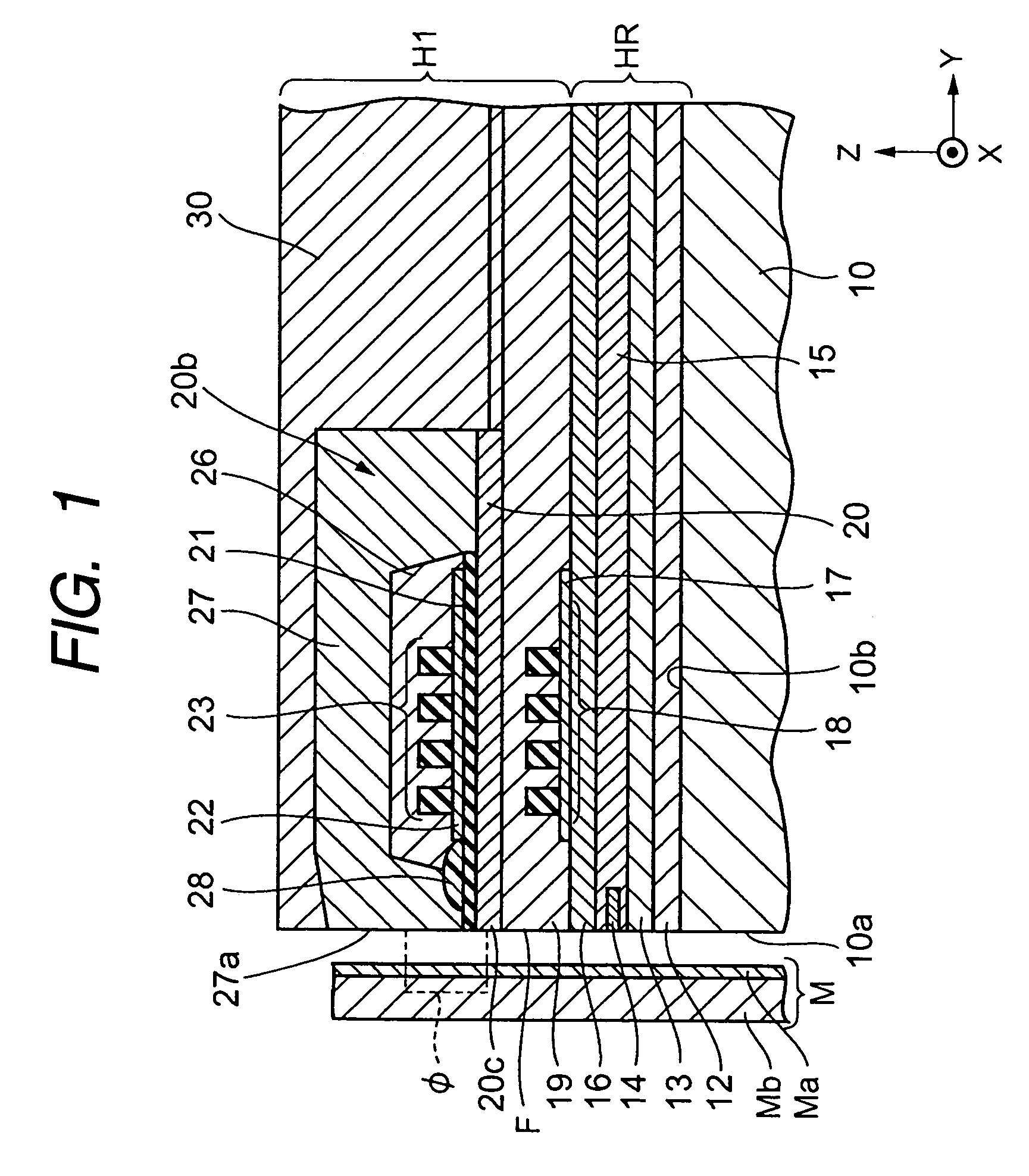
[0020]Therefore, the invention has been made to solve the above problems. It is an object of the invention to provide a magnetic head and a manufacturing method thereof capable of forming upper layer coil pieces to be formed on an insulating layer having a step in a predetermined shape with high precision, reducing the yoke length, and improving the recording efficiency.
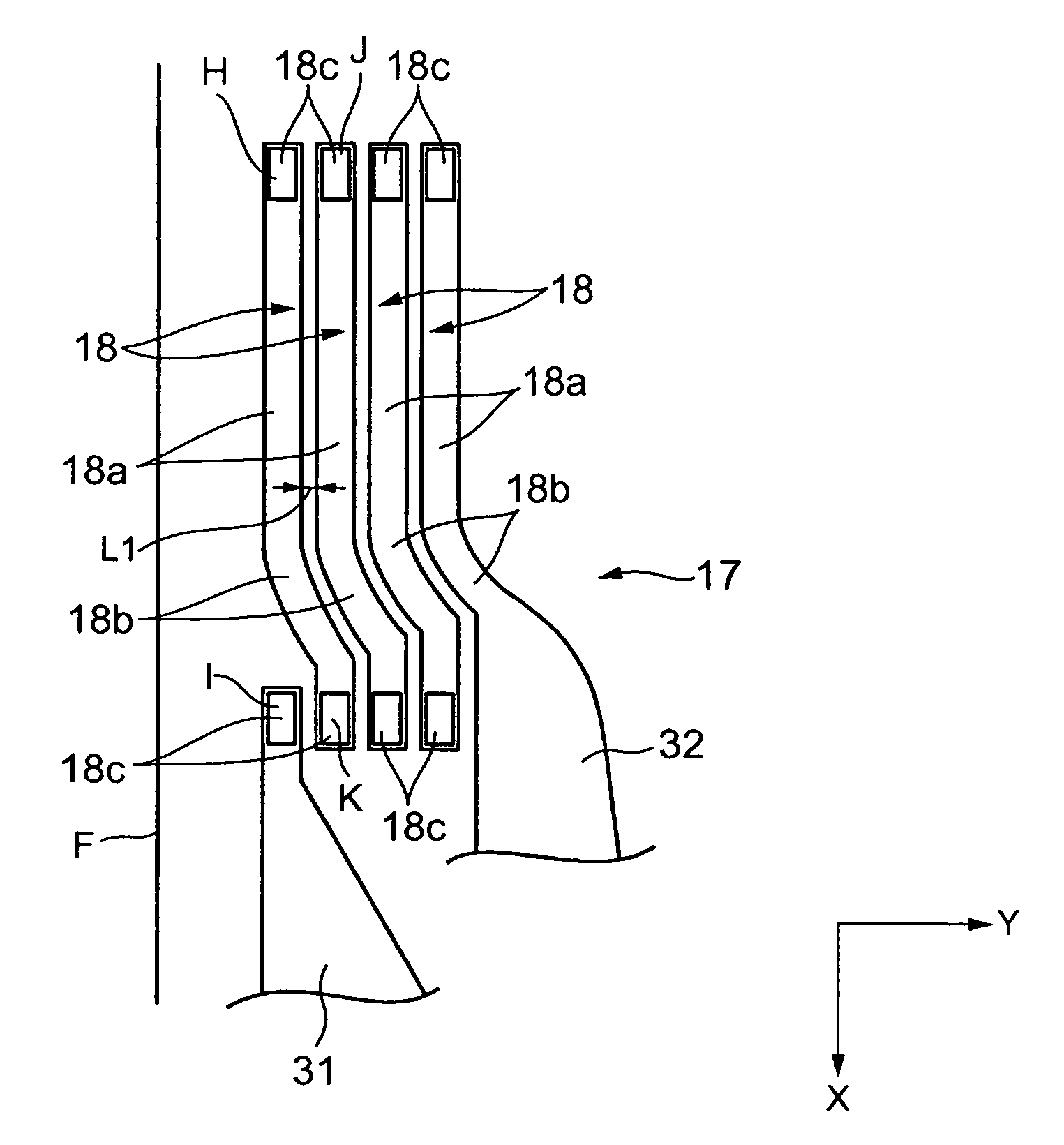
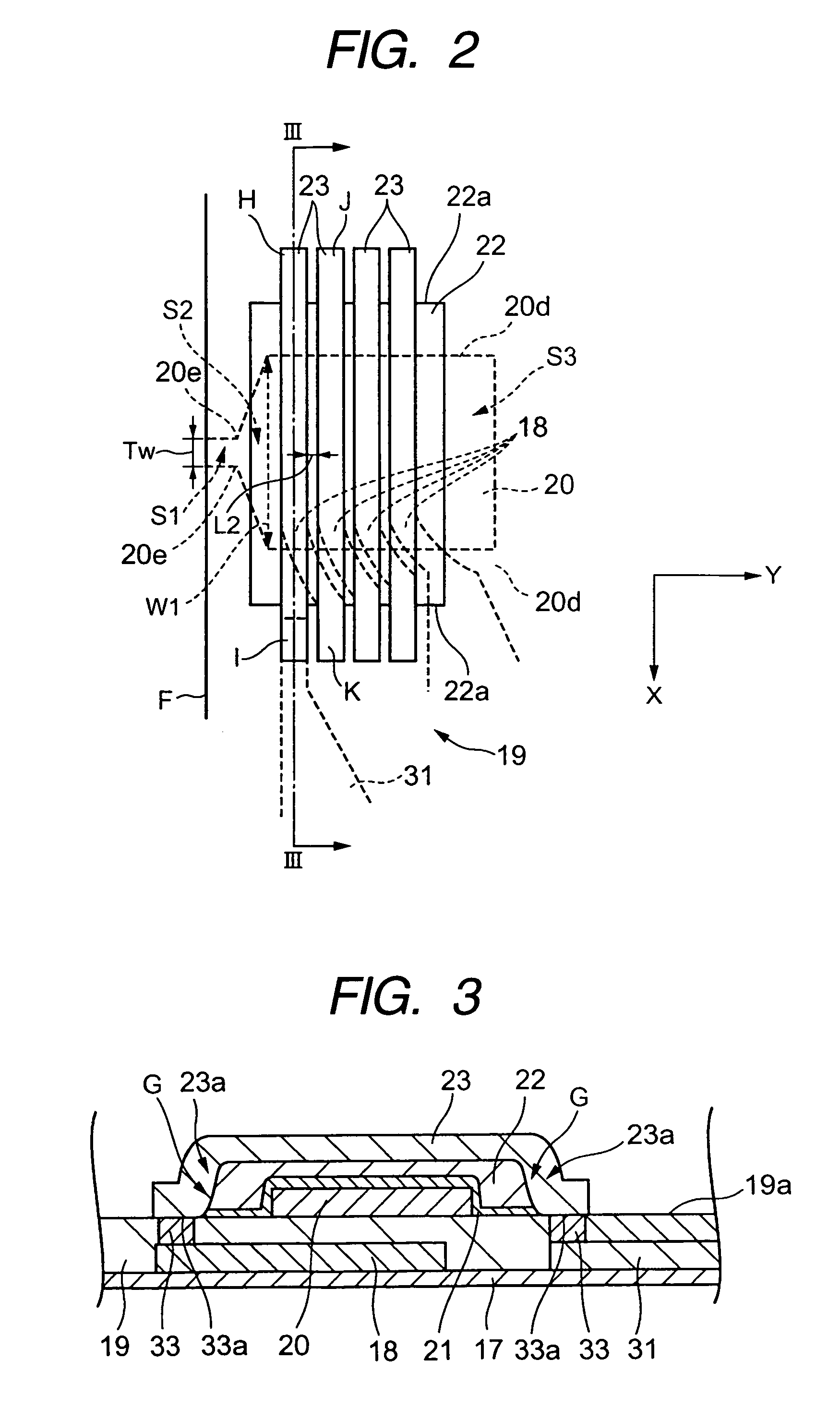
[0027]As described above, the upper layer coil pieces are formed in a direction orthogonal to a direction that both side ends of the first insulating layer extend. Moreover, each of the lower layer coil pieces is formed on the third insulating layer so as to have a straight region extending in the same direction as the upper layer coil pieces. As a result, the upper layer coil pieces can be formed in a predetermined shape from the top of the first insulating layer having a step to the top of the second insulating layer, and the yoke length can be reduced.
[0028]In the above aspect of the invention, it is preferable that a connecting layer be formed on the straight region and the curved region so as to protrude upward, an upper surface of the connecting layer be formed with the same surface as the upper surface of the second insulating layer, and the ends of the upper layer coil pieces be electrically connected to the upper surface of the connecting surface. This allows an electrical connection between the lower layer coil pieces and the upper layer coil pieces to be surely established with a simple structure.
[0029]Further, in the above aspect of the invention, it is preferable that a coil formation surface of the third insulating layer be formed as a planarized surface. This allows the pattern of the lower layer coil pieces to be formed with high precision.
[0044]According to the invention, during step (e), a resist layer is formed from the top of the first insulating layer to the top of the second insulating layer, and when the resist layer is exposed and developed so as to form a punched pattern of the upper layer coil pieces in the resist layer, the punched pattern of the upper layer coil pieces is formed in a direction orthogonal to the direction that both side ends of the first insulating layer in the track width direction extend. Therefore, it is possible to suppress deterioration in pattern precision of the punched pattern caused by irregular deflection as in the related art, and it is possible to form the upper layer coil pieces with high precision. Moreover, since each lower layer coil piece is formed to have a straight region extending in the direction parallel to the track width direction during the step (a), each lower layer coil piece can be formed as nearer to the facing surface as possible, and the length, in the height direction, of the region where the lower layer coil pieces are formed can be reduced. As a result, the yoke length of the magnetic layer can be reduced.

Problems solved by technology

The toroidal coil layer composed of the lower layer coil pieces 1 and the upper layer coil pieces 2 shown in FIGS. 15 and 16, has a problem in that the upper layer coil pieces 2 cannot be formed in a predetermined shape with high precision.
As a result, a problem occurs in that the yoke length of a magnetic layer may easily increase.
Also, there is a problem that the recording efficiency may deteriorate due to an increase in inductance caused by an increase in the yoke length.

Method used


Image

  • Magnetic head having toroidal coil layer and manufacturing method thereof
  • Magnetic head having toroidal coil layer and manufacturing method thereof
  • Magnetic head having toroidal coil layer and manufacturing method thereof

Examples


second embodiment

[0097]FIG. 6 is a partial longitudinal sectional view of a vertical magnetic recording head according to the invention, and FIG. 7 is a partial sectional view when the magnetic head shown is cut along line IV-IV shown in FIG. 6 in the direction parallel to the track width direction (X-direction in the drawing), and the section is viewed from the direction of arrows. In addition, the layers having the same reference numerals as those in FIG. 1 indicate the same layers as those in FIG. 1.

[0098]In FIG. 6, a non-magnetic insulating layer 70 is formed on the main shield layer 16, and a return path layer 71 (first magnetic layer) is formed on the non-magnetic insulating layer 70. A protruding back yoke layer 72 is formed at a rear portion of the return path layer 71 in the height direction, and lower layer coil pieces 18 are formed through a coil insulation base layer 73 (third insulating layer) between the return path layer 71 and the back yoke layer 72. Since an upper surface of the non...

third embodiment

[0101]FIG. 8 is a partial longitudinal sectional view of a thin film magnetic head according to the invention, and FIG. 9 is a partial sectional view when the thin film magnetic head is cut along line V-V shown in FIG. 8 in the direction parallel to the track width direction (X-direction in the drawing), and the section is viewed from the direction of arrows. In addition, the layers having the same reference numerals as those in FIG. 1 indicate the same layers as those in FIG. 1.

[0102]As shown in FIG. 8, a separation layer 40 formed of Al2O3 is formed on the upper shield layer 16, and a lower core layer 41 (first magnetic layer) is formed on the separation layer 40. The lower core layer 41 is formed of a magnetic material such as an NiFe-based alloy. The lower core layer 41 is formed with a predetermined length in the height direction (Y-direction in the drawing) from the facing surface F. A non-magnetic insulating material layer 42 is provided further behind a rear end surface of t...


PUM

PropertyMeasurementUnit
lengthaaaaaaaaaa
lengthaaaaaaaaaa
distanceaaaaaaaaaa

Abstract

First and second magnetic layers of a magnetic head face each other. A toroidal coil layer having upper and lower layer coil pieces (ULCP and LLCP) is wound around one of the magnetic layers. The ULCP extend from a first insulating layer by downward steps to a top of a second insulating layer which is widened at ends of the first insulating layer. Side ends of the first insulating layer extend parallel to a height direction. The ULCP are orthogonal to the side ends. Each of the LLCP is formed on a third insulating layer and has a straight region extending in the same direction as the upper layer coil pieces and a curved region curved toward a facing surface or in a height direction on one end in the track width direction. An end of each of the straight and curved region is connected to an ULCP.

Description

BACKGROUND OF THE INVENTION[0001]1. Field of the Invention[0002]The present invention relates to a toroidal coil layer having, particularly, lower layer coil pieces and upper layer coil pieces, and formed to be wound around a magnetic layer as an axis, and more specifically, to a magnetic head and a manufacturing method thereof capable of forming upper layer coil pieces to be formed on an insulating layer having a step in a predetermined shape with high precision, reducing the yoke length, and improving the recording efficiency.[0003]2. Description of the Related Art[0004]The structure of a toroidal coil layer, which is formed to be wound around the magnetic layer using one magnetic layer serving as an axis, is disclosed in JP-A-5-242429, JP-A-5-250636 and JP-A-5-342529(hereinafter, referred as to “cited references”).[0005]As disclosed in the cited references, the toroidal coil layer is configured to have lower layer coil pieces formed below a magnetic layer serving as an axis and u...

Claims


Application Information

Patent Timeline
Patent Type & Authority Patents(United States)
IPC IPC(8): G11B5/17
CPCG11B5/17G11B5/3123G11B5/3163
Inventor KOBAYASHI, KIYOSHITAKAHASHI, TORU
Owner TDK CORPARATION
Learn More